
Exercise 33: Deploying Brinker Gingival Retractors (Brinker Clamps)
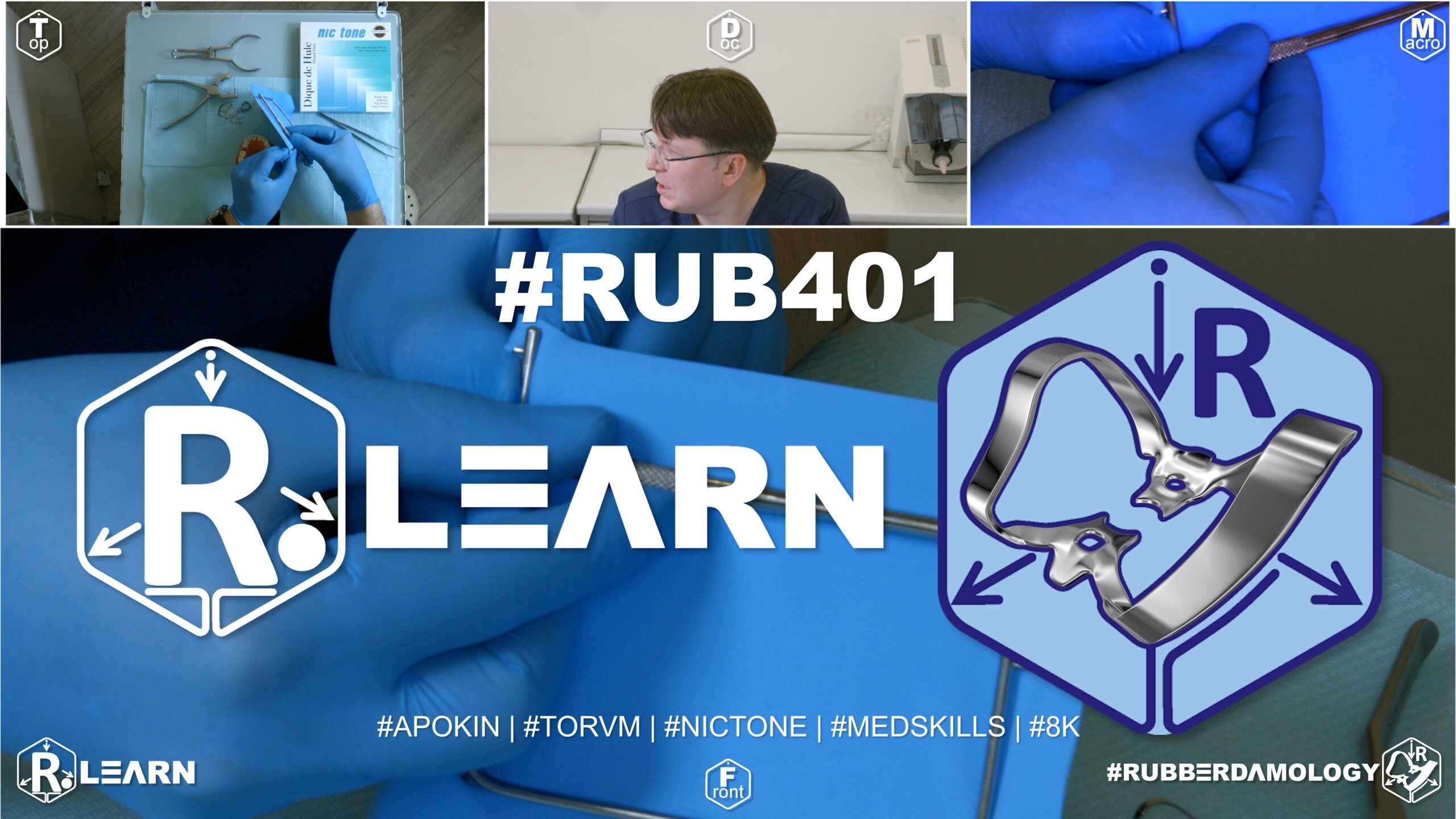
- Target Video Mapping: #RUB401 – Lesson 1 (Video Session 005)
- Core Mechanical Objective: Retract tissues to expose deep Class V defects along the root surface.
- Practical Execution Sequence: Select an active Brinker retractor clamp (such as a B4). Place it onto a tooth with a deep cervical defect, ensuring that the jaw blades slide past the free gingival margin to reveal the entire subgingival floor of the cavity.
1. Exercise Transcription & Notes (Brinker Gingival Retractors Classification & Multi-Retractor Stabilization)
This advanced technical module introduces the Brinker Gingival Retractor System (originally engineered by Dr. Brinker) [02:01]. Dr. Alexander Apokin breaks down the morphological classification of all five classic Brinker designs and demonstrates multi-retractor nesting strategies to safely manage deep cervical (Class V) abfraction decay lines or multiple veneer adhesive bondings [01:00, 06:42, 11:22, 15:37].
- The Brinker System Morphological Inventory:Dr. Apokin outlines the full specialized set produced by Tor VM, noting that unlike standard retention clamps, Brinker retractors are thin-rimmed, spring-tempered, and lack large stabilizing holes on the jaws [02:01, 05:31]:
- Brinker B1 (Molar Retractor): Symmetrical, wide-jaw clamp optimized to seat below the cementoenamel junction (CEJ) of both upper and lower molars [02:56, 03:11].
- Brinker B2 & B3 (Premolar Retractors): Asymmetric pairs designed for upper right/lower left or upper left/lower right bicuspids. One jaw branch is smaller (adapted for the palatal/lingual neck tracking), while the opposing branch is elongated and swept down to push the buccal/vestibular gingiva apically [03:32, 04:00].
- Brinker B4 (Universal/Anterior Retractor): Compact, highly adaptable slim-rimmed clamp originally invented for lower central incisors, but widely adopted globally as the premier universal tool for single-surface Class V decay across all tooth groups [04:36, 05:08].
- Brinker B5 & B6 (Massive Anterior/Canine Retractors): Stiff, dual-bow configurations optimized for heavy tissue displacement on canines and lateral incisors [05:31]. The B5 features flat, low-deflection jaws for tight mandibular anterior segments [07:27], while the B6 is a more massive, high-load variant optimized for thick maxillary tissues [07:16].
- The Hardware Collision Rule & Multi-Retractor Nesting Mechanics:
- The Rear Anchor Law: Dr. Apokin enforces a strict rule: Brinker retractors cannot function independently to secure a rubber dam field [08:22]. They are strictly accessory tissue expanders. The primary tension of the latex canvas must always be handled by a heavy distal anchor clamp (such as a wingless Tor VM W3) seated at least one or two teeth behind your working zone [08:30, 08:40, 13:43].
- The Hardware Collision Bottleneck: When testing the placement of multiple retractors on an upper left model spanning from molar #26 forward across premolars #25 and #24, the structural bows of adjacent retractors can run into each other [13:23]. If a primary anchor clamp is seated too close to the working zone, its metal spring bow will physically block the adjacent Brinker retractor from sliding subgingivally onto the tooth neck [13:23].
- The Strategic Step-Back Solution: To resolve this hardware collision, Dr. Apokin unseats the molar anchor and steps it back one full tooth distally onto tooth #27 [13:43]. This simple modification opens up vital workspace, allowing multiple Brinker retractors to sit smoothly side-by-side [13:53].
- The Rotational Angular Search: When nesting three retractors simultaneously (e.g., a B4 on premolar #25 and a B5 on canine #24), adjacent metal bows can hit each other and lift the jaws off the root surface [15:37, 16:26]. To fix this instability, Dr. Apokin advises performing a rotational angular search [17:32]. Instead of seating all retractors completely straight along the tooth axis, gently twist and angle the retractor bow wire coronally or slightly mesio-distally [17:18, 18:00]. This custom rotation allows the metal loops to slide past each other cleanly, locking all three retractors in a stable, rock-free position [17:32].
2. Mentioned Items & Concepts (Equipment Inventory)
- Complete Brinker Gingival Retractor Kit (Tor VM):
- Brinker B1: Posterior molar retractor [02:56].
- Brinker B2 & B3: Paired asymmetrical bicuspid retractors [03:32, 04:00].
- Brinker B4: Slim universal anterior retractor (Dr. Apokin mandates keeping at least 10 units in stock due to high multi-surface clinical demand) [04:36, 07:59].
- Brinker B5 & B6: Stiff, dual-bow canine/incisor tissue expanders [05:31, 07:16].
- Primary Retaining Hardware:
- Tor VM Wingless Molar Clamp No. W3 (or Double W3): Heavy-duty distal anchor clamp used to isolate the primary canvas tension [08:30].
- Consumables & Core Framework:
3. Key Takeaways & Conclusions
- Brinkers are Tissue Expanders, Not Structural Anchors: Brinker retractors lack large stabilizing holes and wide jaw seats, meaning they cannot support the pulling forces of a rubber dam sheet on their own [08:22]. The primary tension of the canvas must always be secured by a heavy posterior anchor clamp seated at least one or two teeth behind your working zone [08:30].
- Step Back Posterior Anchors to Prevent Hardware Collisions: When nesting multiple Brinker retractors in a tight posterior quadrant, never seat your primary anchor clamp directly adjacent to the working zone [13:23]. The bulky molar bow wire will block your retractors from sliding subgingivally. Always step your primary anchor back one full tooth distally to clear the workspace [13:43].
- Rotational Seating Stabilizes Multi-Retractor Frameworks: When seating multiple Brinker retractors side-by-side, adjacent metal bows will frequently collide and slip loose [15:37]. Perform a rotational angular search, twisting the retractor bow wire slightly mesio-distally [17:32]. This minor adjustment allows the loops to clear each other smoothly, locking all retractors into a completely stable, rock-free position [17:32].
Advanced Cervical Retraction: The Brinker System and Multi-Retractor Nesting Mechanics
Isolating deep subgingival Class V abfraction decay lines or bonding multiple adhesive ceramic veneers requires deep, uniform tissue displacement along the gingival margin. Standard rubber dam retention clamps feature wide horizontal side blocks that can easily snag your canvas and block access to the tooth neck.
+-----------------------------------------------------------------------------+
|                      MULTI-RETRACTOR NESTING MECHANICS                      |
+-----------------------------------------------------------------------------+
|                                                                             |
|   [ THE BASELINE REAR ANCHOR LAW ]                                          |
|    - Brinker retractors cannot support primary canvas tension independently. |
|    - Heavy wingless clamp (W3) must be seated 1-2 teeth behind the zone.   |
|                                                                             |
|   [ COLLISION DEFLECTION: STEP-BACK RULE ]                                  |
|    - Never place the primary molar clamp directly next to your working teeth.|
|    - Step the anchor back 1 tooth distally to open vital retromolar space.  |
|                                                                             |
|   [ STABILIZATION: ANGULAR ROTATION SEARCH ]                                |
|    - Twist the retractor bows slightly mesio-distally.                      |
|    =====> EFFECT: Metal loops clear each other; locks a rock-free seat.      |
|                                                                             |
+-----------------------------------------------------------------------------+
To achieve deep cervical access, the clinician must implement the Brinker Gingival Retractor System. These specialized retractors feature thin-rimmed, spring-tempered jaws that can slide deep subgingivally onto the root neck without tearing your rubber dam sheet.
When executing this protocol, the clinician must strictly follow the Baseline Rear Anchor Law. Brinker retractors lack wide jaw bases and stabilizing holes, meaning they cannot support primary canvas tension independently. Attempting to place a Brinker retractor without a rear anchor will cause the canvas pull to instantly dislodge the hardware, traumatizing the gingival attachment.
The primary tension of the latex sheet must always be secured by a heavy wingless anchor clamp (such as Tor VM W3) seated at least one or two teeth behind your working zone.
Furthermore, when nesting multiple Brinker retractors side-by-side in a tight posterior quadrant, you must implement the Strategic Step-Back Rule to prevent hardware collisions. Placing your primary molar clamp directly adjacent to the working zone will block your retractors, as its bulky metal loop wire stops the Brinker jaws from sliding subgingivally. Stepping the primary molar anchor back one full tooth distally clears the workspace, leaving ample room to position your retractors.
The multi-retractor framework is completed by executing an Angular Rotation Search. Seating multiple retractors completely straight along the tooth axis will cause adjacent metal bows to collide, lifting the jaws off the root surface and loosening the framework.
By gently twisting the retractor bows slightly mesio-distally, the metal loops can clear each other cleanly. This minor adjustment interlocks the hardware into a stable, rock-free framework, ensuring absolute moisture exclusion and maximum visual access for highly predictable subgingival restorations.
Exercise 34: Rigid Stabilization and Compound-Locking of Brinker Retractors

- Target Video Mapping: #RUB401 – Lesson 2 (Video Session 006)
- Core Mechanical Objective: Prevent dangerous clamp movement or root scratching during active treatment.
- Practical Execution Sequence: Heat a green thermoplastic compound stick over an open flame until it becomes soft and moldable. Adapt the softened compound beneath both bows of the seated Brinker clamp, pressing it onto the occlusal surfaces of the adjacent teeth to lock the clamp completely in place.
1. Exercise Transcription & Notes (Brinker Retractor Splinting and Structural Micro-Brush Stabilization)
This advanced operative training module addresses a critical intraoral failure point: stabilizing multiple Brinker universal retractors (B4) when treating deep subgingival Class V (cervical) carious lesions or heavy erosion fields across adjacent teeth [00:52, 02:59].
Dr. Apokin demonstrates that because Brinker retractors are slim-rimmed accessory tools that lack wide, flat surface blocks, high latex canvas tension or active patient lip movements will easily cause them to slip, rock, or dislodge mid-procedure [03:10, 08:33]. To resolve this instability, he introduces two separate clinical stabilizing regimens: a surgical floss-tying loop and a rigid multi-retractor composite splinting technique [08:45, 12:26].
- Baseline Quadrant Layout & Strategic Retractor Seating:
- The baseline moisture barrier is plotted over a maxillary left quadrant model using a high-elasticity Nic Tone sheet mounted asymmetrically onto a standard metal U-frame [01:00, 01:41].
- Four holes are executed template-free along the upper left trajectory [03:58]. To prevent hardware collisions, the primary anchor clamp (Tor VM wingless W3) is stepped back to tooth #27 [02:46]. The sheet is unrolled forward across molar #26, onto premolars #25 and #24 [06:40].
- Dr. Apokin seats two identical Brinker B4 universal retractors onto bicuspids #25 and #24 [02:59]. Crucially, he instructs the clinician to turn the retractor spring bows in opposite directions (the distal retractor’s bow faces backward, while the mesial retractor’s bow faces forward) [08:10]. This deliberate opposing alignment prevents the metal frames from overlapping, opening up a clear workspace between the teeth [08:25].
- Stabilization Option A: The Surgical Floss-Tying Loop:
- If a retractor exhibits minor rocking on a slick root neck, Dr. Apokin demonstrates a rapid, chemical-free option using a long dental floss strand [08:45].
- The floss is looped completely around the heavy metal bow of the primary rear molar clamp (#27) [09:02]. The strands are carried forward, wrapped tightly around the structural bow wires of the Brinker B4 retractors, and tied down with surgical knots (a double knot followed by a single locking knot) [10:45, 11:28]. This tensioned wire network pulls the retractors backward, anchoring them against the rear molar clamp to prevent them from slipping forward [11:59].
- Stabilization Option B: Rigid Multi-Retractor Composite Splinting (The Micro-Brush Law):
- For extensive deep cavity preparations or high-tension cases where floss loops might slip, Dr. Apokin introduces a highly reliable technique using a standard disposable micro-brush and flowable resin composite [12:26].
- The Micro-Brush Trimming Protocol: The clinician takes a standard micro-brush and uses a scalpel or handpiece disk to cut away the unused fuzzy head, trimming the plastic handle to match the linear distance between the two Brinker bows [13:29, 13:41]. To maximize bond strength, he advises cutting small undercuts into the plastic handle using a bur, which creates a strong mechanical lock for the composite [13:41, 15:09].
- The Palatal Splinting Rule: Place the trimmed plastic handle straight across the adjacent steel bows of the Brinker retractors, bridging the gap between them [14:16]. Crucially, Dr. Apokin issues a strict rule: always splint the micro-brush handle across the palatal/lingual aspect of the retractor bows—never on the buccal/vestibular side [16:00]. Splinting on the buccal side creates an immediate roadblock, blocking your access and leaving no room to manipulate your composite modeling instruments [16:13]. Palatal splinting keeps the entire buccal workspace open and clear [16:27].
- Flowable Injection and Curing: Two drops of flowable resin composite are injected over the plastic-to-steel contact points [14:30]. The material is light-cured with a polymerizing lamp [14:57, 15:23]. This creates a rigid structural beam that locks the two standalone retractors into a single, highly stable, rock-free unit that cannot flip or slip off the tooth necks under active tension [15:41]. Complete the barrier by folding a standard catchment envelope [16:41, 18:10].
2. Mentioned Items & Concepts (Equipment Inventory)
- Advanced Structural Sealing Hardware:
- Splinting Consumables & Hand Tools:
- Standard Plastic Micro-Brush: Fuzzy tip cut away; handle repurposed as a rigid horizontal splinting beam [12:26, 13:58].
- Flowable Resin Composite & Polymerization Light: Used to chemically bond the plastic handle to the steel bows [14:30, 14:57].
- Surgical Scalpel Blade / Handpiece Diamond Disk: Hand tools used to trim handles and cut retentive undercuts [13:41, 13:58].
- High-Visibility Dental Floss: Used to tie stabilizing rear loops and check proximal contacts [04:41, 08:45].
- Consumables & Core Framework:
3. Key Takeaways & Conclusions
- Opposing Bow Directions Prevent Hardware Overlap: When placing multiple Brinker B4 retractors side-by-side on adjacent teeth, always turn the spring bows in opposite directions [08:10]. Facing the distal retractor backward and the mesial retractor forward stops the metal frames from overlapping, opening up a clear visual workspace between the crowns [08:25].
- Buccal Splinting Blocks Instrument Workspace Access: Never splint a micro-brush handle across the buccal/vestibular aspect of your retractor bows [16:00]. This creates an immediate roadblock, leaving zero room to maneuver your composite modeling instruments. Always bond the splinting bar across the palatal/lingual loops to preserve a completely wide-open buccal working path [16:13, 16:27].
- Undercuts Maximize Plastic-to-Steel Bond Strength: When cutting a plastic micro-brush handle to use as a splinting bar, always use a bur to cut small undercuts into the plastic body [13:41]. These micro-grooves provide a strong mechanical lock for the flowable resin composite, ensuring the rigid beam remains securely bonded to the slick steel bows throughout heavy procedure manipulation [15:09, 15:41].
Structural Multi-Retractor Splinting: The Micro-Brush Law and Lingual Arc Stabilization
When treating extensive Class V cervical lesions, root erosions, or abfractions across adjacent teeth, placing multiple Brinker universal retractors (B4) side-by-side is required to achieve deep, uniform soft-tissue retraction. However, because Brinker retractors are slim-rimmed accessory tools that lack wide, flat surface blocks, high latex canvas tension or active patient lip movements can easily cause the hardware to rock, slip, or dislodge mid-procedure, risking immediate contamination of your bonding surface.
+-----------------------------------------------------------------------------+
|                      RIGID MULTI-RETRACTOR SPLINTING PATHWAY                 |
+-----------------------------------------------------------------------------+
|                                                                             |
|   [ EXTENDED BACKLINE ANCHOR ]                                              |
|    - Primary wingless clamp (W3) steps back 1 tooth to clear the segment.   |
|                                                                             |
|   [ OPPOSING BOW ORIENTATION ]                                              |
|    - Distal retractor bow faces BACKWARD; mesial retractor bow faces FORWARD.|
|    =====> EFFECT: Prevents hardware overlap; opens the interproximal zone.  |
|                                                                             |
|   [ THE PALATAL SPLINTING LIGAMENT ]                                        |
|    - Cut retentive undercuts into a trimmed plastic micro-brush handle.     |
|    - Bond handle across the PALATAL/LINGUAL aspects of the steel bows.      |
|    =====> FAILURE AVOIDANCE: Buccal splinting blocks instrument access.     |
|    =====> SUCCESS EFFECT: Locks retractors into a single rock-free unit.   |
|                                                                             |
+-----------------------------------------------------------------------------+
To achieve complete stability, the clinician must implement The Rigid Multi-Retractor Splinting Protocol. The workflow begins by stepping your primary posterior anchor clamp (such as Tor VM W3) back one full tooth distally to clear the segment.
The Brinker B4 retractors are then seated onto the adjacent tooth necks, ensuring that the spring bows are turned in opposite directions: the distal retractor’s bow faces backward toward the throat, while the mesial retractor’s bow faces forward toward the lips. This deliberate opposing alignment prevents the metal frames from overlapping, opening up a clear visual workspace between the crowns.
To lock these standalone retractors into a single, rock-free unit, the clinician implements The Micro-Brush Splinting Technique. A standard disposable micro-brush handle is trimmed to match the linear distance between the adjacent metal loops. Crucially, the clinician must use a bur to cut small undercuts into the plastic handle body; these micro-grooves provide a strong mechanical lock for the flowable resin composite, ensuring a high-strength bond against the slick steel wires.
The trimmed plastic handle is then placed straight across the steel bows, bridging the gap between them. Crucially, the clinician must strictly follow The Palatal Splinting Law, bonding the plastic handle across the palatal/lingual aspect of the retractor bows—never on the buccal/vestibular side.
Splinting on the buccal side creates an immediate roadblock, blocking your line of sight and leaving no room to maneuver your composite modeling instruments. Injecting two small drops of flowable resin composite over the palatal plastic-to-steel joints and light-curing them creates a rigid structural beam. This customized beam locks the retractors into a single, unyielding framework that cannot flip or slip off the tooth necks, preserving an absolute moisture seal and opening up a wide, unhindered buccal working path for highly predictable direct composite restorations.
Exercise 35: Total Mandibular Anterior Cervical Retraction Block (35 to 45)
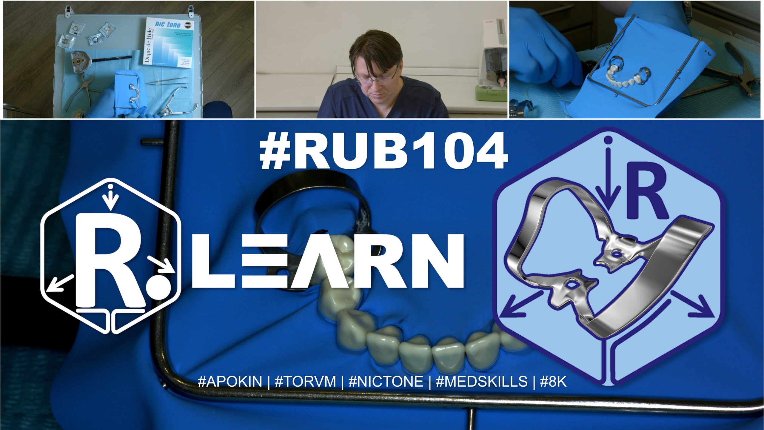
- Target Video Mapping: #RUB401 – Lesson 3 (Video Session 014)
- Core Mechanical Objective: Retract tissues across the entire lower anterior segment for multi-unit cervical therapy.
- Practical Execution Sequence: Punch a continuous six-hole sequence for the lower front teeth. Guide the rubber dam sheet deep into the anterior sulcus, securing both ends with active clamps to create a clear, dry horizontal shelf across the entire front segment.
1. Exercise Transcription & Notes (Full Lower Anterior Arch Isolation & Asymmetric Corner Punch Coding)
This advanced technical module covers full lower anterior arch isolation, specifically spanning from the lower left second premolar to the lower right second premolar (Teeth #35 to #45) [01:11, 06:11]. Dr. Apokin outlines template-free plotting rules for the lower jaw, explains how to avoid layout distortion, and details a non-destructive method for marking canvas corners using asymmetric punch coding [04:59, 09:25].
- Mandibular Anterior Arch Layout Constraints:
- The instructor mounts a high-strength Nic Tone medium latex sheet asymmetrically onto a standard metal U-frame [01:25, 02:40].
- The Mandibular Margin Law: For full lower arch anterior isolations, all punctures must be mapped low down, near the lower third boundary line of the frame window [03:59]. Crucially, Dr. Apokin warns that placing the layout high or dead-centered inside the frame window is a major mistake [03:08, 03:32]. It leaves a loose, drooping canvas flap at the bottom that cannot form a proper catchment envelope, while pulling the sheet tight over the patient’s nose and blocking their breathing [03:40]. Keeping the holes low leaves a wide, solid latex shield at the top to cover the maxilla and keep the airway open [03:15].
- He executes nine inline holes template-free to map the full bicuspid-to-bicuspid segment (#35 to #45) [06:11]. He clicks a small hole setting on the Sanctuary punch wheel for the lower central and lateral incisors (#31, #32, #41, #42), stepping up to a medium diameter setting for the canines (#33, #43) and premolars (#34, #35, #44, #45), maintaining a strict 5 mm inter-hole distance [04:36, 07:01, 07:31].
- Asymmetric Corner Punch Coding Architecture:
- The Orientation Bottleneck: When managing a long, multi-hole canvas loaded with multiple clamps outside the mouth, the material easily bunches up and twists [09:58]. In a live patient scenario, this bunching makes it highly confusing to tell which corner goes to the upper left or lower right prongs, wasting time and causing alignment errors [10:16, 11:00].
- The Coding Solution: To create a permanent, foolproof layout guide without using a felt marker, Dr. Apokin utilizes the largest hole on his punch wheel to clip asymmetric coding holes into the excess border margins of the sheet before entering the mouth [09:25]. He punches two holes into the upper left corner margin and one hole into the upper right corner margin [09:25].
- When the pre-loaded sheet is carried intraorally and unrolled, the dentist can instantly match the coded margins to the frame prongs within seconds, entirely eliminating mid-procedure confusion [11:22, 11:59].
- Dual Wingless Seating & Floss Inversion Path:
- Dr. Apokin pre-tests the mechanical stability of two low-profile wingless clamps on the terminal anchoring premolars (#35 and #45) to ensure a rock-free four-point seat [07:51].
- The Clamps-In-Dam Delivery Method: Outside the mouth, the steel springs of both wingless clamps are pushed through the terminal holes (#35 and #45) like rings until the rubber tightly encircles their jaws [08:58].
- The bunched clamp-dam unit is carried intraorally, seating the left anchor clamp onto tooth #35 first, followed by the right anchor clamp onto tooth #45 [10:16, 10:43].
- The coded corners are quickly unrolled and hooked over the frame prongs [11:22]. Using a blunt plastic tool or an explorer probe, the rubber dam margins are flipped smoothly beneath the clamp jaws [12:19, 12:28].
- Dental floss is then passed systematically through the intermediate contact points, rolling the septa subgingivally from the left premolar all the way across to the right premolar to achieve an absolute moisture seal [12:57, 13:58].
- Correction Adjustment: If the high tension of the long canvas pull creates a microscopic gap or lifting force around the anchor teeth, simply expand the clamp jaws slightly with forceps, lift the assembly, and re-seat it firmly into the deep cervical track of the root neck [15:35, 15:44]. Complete the setup by folding a standard catchment envelope [18:01].
2. Mentioned Items & Concepts (Equipment Inventory)
- Retaining Hardware Retainers:
- Consumables & Core Bench Kit:
- Nic Tone Medium Latex Canvas & Metal U-Frame: Moisture barrier processing standards [01:25, 03:59].
- Sanctuary Dental Perforation Punch & Forceps: High-precision processing tools [01:25, 09:25].
- High-Visibility Dental Floss & Probe Tool: Used for structural contact flossing, tying secure ligatures, and guiding subgingival inversion [01:46, 12:19, 16:41].
- Anatomical Targets:
3. Key Takeaways & Conclusions
- Centered Punctures Cause Mandibular Airway Blocks: Never punch your rubber dam layout in the center of the sheet for lower arch restorations [03:08]. This leaves a huge, loose flap of rubber at the bottom that cannot form a proper catchment envelope, while pulling the sheet tight over the patient’s nose and suffocating their breathing [03:40]. Always keep your punctures low, near the lower third boundary line of the frame window [03:59].
- Asymmetric Corner Punch Coding Guides Orientation: To prevent the rubber sheet from twisting and bunching up when pre-loading multiple clamps outside the mouth, clip asymmetric coding holes into the excess margins [09:25]. Punching two holes on the upper left margin and one on the upper right allows you to instantly align the corners with the frame prongs within seconds [11:22, 11:59].
- Systematic Inversion Secures Full Arch Moisture Seals: When isolating a long multi-unit segment from premolar to premolar, you must use dental floss systematically through every intermediate contact point [12:57]. This systematic flossing rolls the rubber septa completely subgingivally across the entire anterior segment, eliminating any micro-gaps and guaranteeing an absolute moisture seal for multiple adhesive veneer bondings [13:58].
Full Lower Anterior Arch Isolation: Asymmetric Corner Punch Coding and Mandibular Airway Management
Isolating the full lower anterior arch segment spanning from the lower left second premolar to the lower right second premolar (#35 to #45) is a fundamental prerequisite for executing predictable multi-unit adhesive restorations, cosmetic ceramic veneer bondings, or extensive structural composite scaling. Managing a long, high-tension nine-tooth segment requires the clinician to strictly manage rubber dam geometry to prevent canvas distortion and safeguard patient respiration.
+-----------------------------------------------------------------------------+
|                      FULL MANDIBULAR ARCH ISOLATION DESIGN                  |
+-----------------------------------------------------------------------------+
|                                                                             |
|   [ DEAD-CENTER PUNCH ERROR ]                                               |
|    - Placing layout in the center of the sheet for lower restorations.       |
|    =====> FAILURE: Suffocates patient's nose; bottom canvas collapses.       |
|                                                                             |
|   [ LOW-THIRD PERFORATION LAW ]                                             |
|    - Map all nine inline punches low along the lower third boundary line.   |
|    =====> EFFECT: Keeps the nasal airway fully clear; forms a catchment pocket.|
|                                                                             |
|   [ ASYMMETRIC CORNER PUNCH CODING ]                                        |
|    - Upper Left Margin: 2 punch holes | Upper Right Margin: 1 punch hole.  |
|    =====> EFFECT: Instant orientation guide; completely eliminates twists.   |
|                                                                             |
+-----------------------------------------------------------------------------+
A severe technical error commonly made during full arch lower layouts is punching the perforation pattern dead-center inside the rubber dam sheet. This central placement pulls the latex taut directly over the maxilla, completely covering the patient’s nose and blocking their breathing. Simultaneously, it leaves a loose, drooping flap of excess rubber at the bottom that collapses and fails to form a proper fluid catchment envelope.
To ensure complete respiratory comfort and structural stability, the clinician must implement The Low-Third Perforation Law. All nine inline punctures must be mapped low down, near the lower third boundary line of the frame window. This leaves a wide, solid latex shield at the top of the frame to safely cover the maxillary teeth while keeping the patient’s nasal airway completely open and open.
The next mechanical challenge is managing a long multi-hole canvas pre-loaded with multiple clamps outside the mouth. The high elastic pull causes the loose rubber to twist and bunch up. When carried intraorally, this bunching makes it highly confusing to distinguish the upper left corner from the right corner, resulting in alignment errors.
To create an instant, permanent orientation guide without using a felt marker, the clinician implements Asymmetric Corner Punch Coding. Using the largest hole on the punch wheel, two holes are clipped into the excess upper left margin border, and one hole is clipped into the upper right margin before entering the mouth. This asymmetric map allows the correct corners to be matched to the frame prongs within seconds, entirely eliminating mid-procedure confusion.
The layout is secured by pushing the steel springs of low-profile wingless bicuspid clamps through the terminal holes (#35 and #45) outside the mouth, carrying the pre-loaded block intraorally, and locking the jaws onto the anchoring premolar necks. The coded corners are quickly unrolled over the frame prongs, and dental floss is passed systematically through every intermediate contact point across the entire bicuspid-to-bicuspid segment. This systematic flossing rolls the thin rubber septa completely subgingivally, eliminating any micro-gaps and establishing a flawless, bone-dry operational field for predictable multi-unit adhesive restorations.