
Exercise 12: Split-Dam Techniques and Variational Slit Protocols
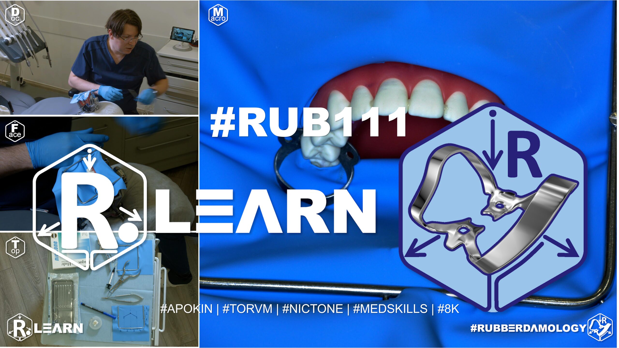
- Target Video Mapping: #RUB111 – Lesson 1 (Video Session 026)
- Core Mechanical Objective: Expose highly broken-down front teeth without risking tears.
- Practical Execution Sequence: Execute controlled scissor cuts to connect multiple holes into a continuous oval slot. Stretch the open slot over a crowded anterior segment, then apply light-cured liquid dam gel along the borders to seal the margins.
1. Exercise Transcription & Notes (The Split-Dam Isolation Protocol for Fixed Prosthetics)
Dr. Alexander Apokin demonstrates the “Split-Dam” technique for the maxillary anterior arch. This advanced procedure is used when a patient has a multi-unit ceramic bridge block or fixed prosthetic crowns where the interproximal spaces are fully blocked or fused together, making standard flossing impossible.
To simulate this clinical roadblock on a Med Skills model, flowable composite is deliberately applied between the front teeth to create a solid, fused segment.
- The Flawed “Three-Hole” Split Pattern (Unstable Variant):
- The instructor critiques a common split-dam technique frequently shown on dental internet channels, where only three holes are punched (one for each anchor premolar and one in the center) and then slit horizontally.
- The Core Failure: When a wingless clamp (like W2) is placed on the first premolars and a three-hole slit canvas is stretched over it, high structural tension causes the loose rubber sheet to instantly snap back and detach. Without anchoring tabs, the sheet wrinkles up, leaks fluids, slips off the teeth, and fails completely under active tension.
- The “Five-Hole” Split-Dam Technique (The Predictable Master Method):
- To achieve absolute structural stability under high elastic tension, Dr. Apokin introduces the five-hole split pattern.
- The Layout: Mount a medium Nic Tone latex sheet onto a metal U-frame with equal side boundaries and a wide lower canvas slack zone. Use a marker to track the vertical midline.
- Perforation Pattern: Five medium-diameter holes are punched in a precise row: two outer terminal anchor holes (for teeth #15 and #25), two intermediate structural relief holes, and one central hole.
- The Cutting Rule: Use surgery scissors to carefully cut a continuous horizontal slit connecting the inner three holes. Leave the remaining rubber webs between the intermediate holes and the outer terminal anchor holes fully intact. These small rubber bridges act as structural tension tabs.
- Assembly, Sub-Lip Padding, & Palatal Silicone Anchoring:
- The winged premolar clamps (Tor VM No. 2) are pre-loaded into the separate, intact outer anchor holes of the canvas outside the mouth.
- The clamp-dam unit is carried into the mouth, seating the clamps onto the premolars (#15 and #25). The intact rubber tabs securely anchor the sheet to the tooth necks, completely isolating the tension of the frame.
- Pass dental floss through the only accessible distal contact points (#14–#15 and #24–#25) to complete the outer inversion.
- The Sub-Lip Cotton Stabilizer: Pack two thick dental cotton rolls high under the patient’s upper lip, resting them directly over the facial canvas. The natural muscular pressure of the patient’s lip presses down onto the cotton rolls, locking the facial rubber dam flap snugly against the underlying crowns and preventing any fluid from leaking through.
- Palatal Hermetic Adhesion: Because there are no intermediate holes to invert on a split dam, the palatal side can gap and leak fluid under airflow. To seal this, Dr. Apokin injects a bead of regular heavy-body or bite-registration silicone from an automix gun directly along the junction where the palatal sheet meets the artificial gingival base. Once polymerized, this silicone block creates a fluid-tight seal. Complete the routine by folding the lower canvas upward into a catchment envelope.
2. Mentioned Items & Concepts (Equipment Inventory)
- Consumables & Adhesives:
- Nic Tone Medium Latex Sheets: Durable elastic sheets capable of stretching across wide multi-unit spans without tearing.
- Automix Silicone Elastomer: Material injected onto the palatal surfaces to act as a tight moisture barrier.
- Flowable Composite: Used here to deliberately connect the contacts, creating a mock fixed prosthetic bridge block.
- Hardware Retainers & Tools:
- Tor VM Winged Clamps No. 2: Symmetric premolar clamps chosen for their wide stabilization wings, which keep the cut canvas stretched open.
- Tor VM Wingless Clamps W2: Used in the initial demonstration to show how three-hole patterns fail on wingless designs.
- Dental Cotton Rolls: Placed beneath the upper lip to serve as muscular pressure anchors.
- Surgical Scissors & Metal U-Frame: System defaults.
- Clinical Terminology:
- Split-Dam Isolation: Slitting a row of punch holes into a single open slot to isolate a continuous bridge block where interproximal spaces are fused.
- Fixed Prosthetic Bridge Block: A permanent dental bridge spanning from premolar to premolar.
3. Key Takeaways & Conclusions
- Three-Hole Split Designs Fail under Active Tension: Avoid using simple three-hole split patterns on wingless clamps. Without intermediate rubber tabs to anchor the material to the tooth necks, the high tension of the frame will pull the sheet away from the teeth, resulting in leaks and isolation failure.
- Intact Rubber Tabs Provide Structural Stability: The five-hole split design solves the tension problem by leaving the rubber webs between the anchor holes and the central slit completely intact. These small rubber bridges securely anchor the sheet to the premolars, isolating the elastic pull of the frame and preventing leaks.
- Lips and Silicone Create the Moisture Seal: Because a split dam lacks interproximal septa, you must use alternative sealing methods. Placing cotton rolls high under the patient’s lip uses natural muscle pressure to seal the facial canvas, while injecting a bead of silicone along the palatal margin creates a durable, fluid-tight moisture barrier.
This section integrates Exercise 12 into your textbook track, introducing the “Split-Dam” (or “Slit-Dam”) technique. This is an advanced operative strategy for handling complex tooth positions, orthodontic appliances, or segments where standard individual perforations are anatomically impossible or prone to failure.
Split-Dam Techniques and Variational Slit Protocols
The “Split-Dam” technique abandons the paradigm of individual perforation holes in favor of a continuous incisional window. While individual holes are the standard for 90% of clinical cases, the Split-Dam is a surgical-grade solution for the remaining 10%: severely crowded teeth, malpositioned teeth, or segments cluttered with fixed orthodontic brackets where individual isolation would result in excessive tearing of the latex septa.
+-----------------------------------------------------------------------------+
|                      THE SPLIT-DAM ARCHITECTURE                             |
+-----------------------------------------------------------------------------+
|                                                                             |
|   [ THE STRESS-RELIEF GEOMETRY ]                                            |
|    - Slit corners MUST be rounded. Sharp 90-degree corners act as           |
|      "tear-starters" under high-tension arch loads.                         |
|                                                                             |
|   [ THE SEALING PARADOX ]                                                   |
|    - A slit is not a seal; it is a void. The seal must be re-established     |
|      via interdental wedges, floss ligatures, or specialized putty.         |
|                                                                             |
|   [ THE PAPILLA "TOURUNIQUET" RISK ]                                        |
|    - Improper slit placement compresses the interdental papilla.            |
|    =====> EFFECT: Risk of ischemia, necrosis, and permanent recession.      |
|                                                                             |
+-----------------------------------------------------------------------------+
The Surgical Philosophy of the Slit
A split-dam is created by connecting multiple perforation holes with a scalpel or by performing a deliberate incision between two anchors.
- When to Employ: This protocol is indicated when the interproximal contact is so tight that the rubber septa constantly tears, or when the teeth are so overlapped that individual isolation creates a “tent” effect that prevents the dam from reaching the cervical margin.
- The Scalpel Technique: Always use a fresh No. 11 or No. 12 scalpel blade. The incision should be clean and continuous. Crucially, the endpoints of the slit must be rounded—do not finish with a sharp cut, as the tension of the rubber dam frame will cause the slit to propagate into a massive, unrepairable tear.
Re-establishing the Seal
Unlike individual perforations, which rely on the elastic memory of the rubber to seal the neck, a split-dam creates a gap that must be mechanically closed.
- The Wedge-Ligature Integration: The split-dam requires supplementary sealing agents. Interdental wedges (wood or plastic) must be placed firmly to press the rubber against the tooth surfaces.
- Floss Ligatures as Barriers: In areas where wedges are insufficient, a floss ligature is mandatory. By passing the floss through the slit and tying it around the cervical necks of the isolated teeth, you force the rubber dam “flaps” against the tooth structure, effectively recreating the moisture seal lost by the incision.
Anatomical Preservation
The greatest risk of the split-dam technique is iatrogenic damage to the soft tissue. Because the dam is no longer held by individual septa, the rubber flaps can easily impinge upon the interdental papilla.
- The Papilla Audit: Immediately after placing the split-dam, use a periodontal probe to lift the margins of the slit and verify that the rubber is not compressing the papilla. If the rubber is “trapped” under the papilla, it acts as a tourniquet, cutting off the blood supply. This must be corrected with a blunt instrument or, in extreme cases, by enlarging the slit to allow the rubber to drape passively over the tissue.
Clinical Utility in Orthodontics
The split-dam is frequently the only viable method for isolating a segment containing fixed orthodontic brackets. By creating a continuous slit, the clinician can slide the rubber dam over the brackets, avoiding the nearly impossible task of threading the rubber through the crowded wire-bracket complex. Once in place, the slit is “closed” with interdental wedges and a sealant (such as liquid rubber dam or flowable composite), creating a perfectly dry field for adhesive procedures.
Mastery of Exercise 12 demonstrates that the clinician is no longer reliant on “perfect” anatomy. You have now learned how to engineer the isolation to fit the clinical reality, regardless of the complexity of the dental arch.
Exercise 13: Preparing the Field for Fixed Orthodontic Retainer Bonding
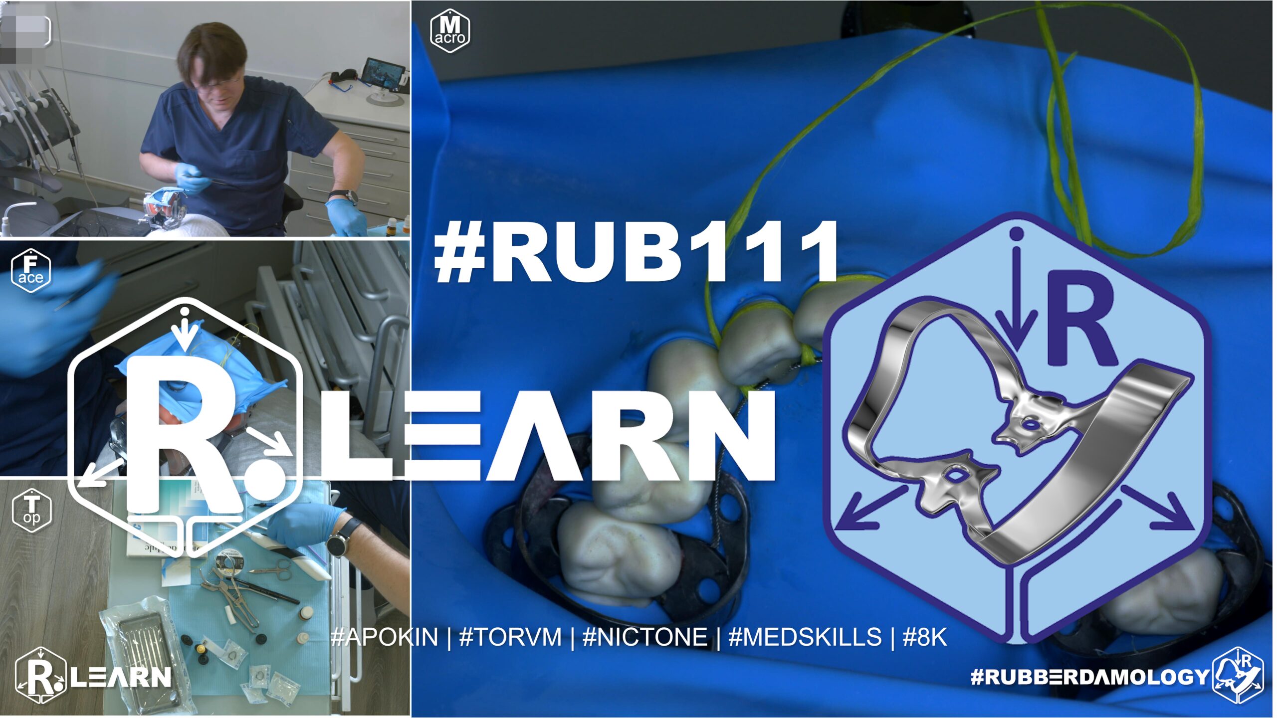
- Target Video Mapping: #RUB111 – Lesson 2 (Video Session 029)
- Core Mechanical Objective: Ensure a bone-dry lingual substrate for clear bonding.
- Practical Execution Sequence: Punch the holes slightly more labially than normal. Invert the latex cuff completely toward the palatal/lingual aspect, ensuring that the entire lingual enamel field is exposed and free from breath moisture or sulcular fluid.
1. Exercise Transcription & Notes (Orthodontic Retainer Bonding via Advanced Moisture Isolation)
Dr. Alexander Apokin demonstrates a highly complex multidisciplinary protocol combining advanced rubber dam isolation, micro-abrasive surface texturing, and three-component adhesive chemistry to permanently bond a flat-profile orthodontic retention wire across the palatal aspect of the maxillary anterior arch (Teeth #15 to #25) [00:47, 03:11].
- Pre-Isolation, Layout, & Arch Extension:
- The instructor underscores a basic dental law: to perform predictable, long-term adhesive bonding, a rubber dam moisture barrier is absolutely mandatory [01:00]. Furthermore, utilizing an aluminum oxide micro-blaster intraorally to clean the enamel is completely unsafe for the patient’s airway without a protective rubber barrier in place [01:10, 16:18].
- To keep the entire palatal workspace wide open and free from metallic projections, Dr. Apokin extends the isolation span beyond the canines to the second premolars (#15 and #25) and selects compact wingless premolar clamps (Tor VM W2) [03:11]. Canines are avoided as primary anchors due to their slippery, unstable morphology [02:42].
- A medium-density Nic Tone latex sheet is pre-tensioned onto a metal U-frame [01:33, 04:02]. Ten symmetrical, template-free holes are punched in a precise row along the upper quadrant boundary [04:54, 06:43].
- The wingless W2 clamps are pre-loaded directly into the terminal premolar holes outside the mouth, and the assembly is transferred into the oral cavity [07:07, 08:07].
- The intermediate canvas is unrolled over the anterior segment. Because orthodontic patients typically exhibit some interdental space or loose contact points following tooth movement, sliding the rubber sheet septa between the teeth is highly straightforward [09:30].
- Palatal Clearance & Secondary Retraction:
- Managing Palatal Vision Blocks: On the palatal aspect of maxillary lateral incisors, the rubber dam sheet can sometimes gap, bunch up, or lift away from the cingulum under elastic tension. This loose rubber physically blocks the dentist’s visual line of sight and prevents proper wire adaptation [11:02].
- The Accessory Retractor Wedge: To correct this, Dr. Apokin spreads the rubber margin apically using an explorer probe and seats secondary Brinker B4 retractors onto the facial necks of the lateral incisors [11:14]. The mechanical squeeze of the Brinker jaws forces the palatal rubber material down and back into the cervical sulcus, flattening the sheet and creating an unhindered, crystal-clear line of sight along the entire palatal cingulum path [11:31].
- Precision Wire Measurement:
- To accurately measure the required length of the reinforcement wire without bending it prematurely, Dr. Apokin lays a standard strand of dental floss smoothly along the palatal curves from #15 to #25 [12:55, 13:31].
- He marks the terminal spans on the floss using a felt marker [13:56]. The floss is then laid flat on the bench next to a flat retention wire (Orthodontic Retainer Wire) to transfer the marks precisely before cutting the wire with heavy cutters [14:25, 15:50].
- Subsurface Texturing & Multi-Component Chemistry:
- The palatal enamel surfaces are micro-blasted with aluminum oxide particles, followed by selective phosphoric acid etching [16:18, 17:08]. The catchment envelope collects all water and debris, keeping the operating field completely clean [18:16].
- Dr. Apokin utilizes a meticulous three-component adhesive protocol to optimize bond strength [19:39]:
- Syntac Primer: Applied continuously across all etched dots and thoroughly air-thinned to evacuate solvent carriers [20:01, 20:53].
- Syntac Adhesive: Scrubbed over the primed enamel to establish deep resin tags, followed by air-drying [21:08, 21:32].
- Heliobond Resin: The final unfilled fluid resin layer is brushed thinly over the surfaces and light-cured continuously [21:42, 23:08].
- The Floss-Loop Wire Retention Technique:
- Dr. Apokin critiques old techniques that involve using pieces of surgical glove rubber to hold the wire in place, labeling them as cumbersome time-wasters [25:08, 25:54]. Instead, he introduces a streamlined, floss-only retention technique [26:03].
- He threads a strand of dental floss through the interproximal spaces of the central incisors, hooks it under the retention wire, and pulls the loop back toward the facial/vestibular side [28:04].
- By pulling these loops taut, the floss creates intense mechanical tension that pulls the wire tight against the palatal enamel [29:39]. This acts as a hands-free assistant, holding the wire completely immobile while leaving the entire palatal area clear for composite adaptation [29:52].
- Once the floss loops lock the wire in place, the Brinker B4 retractors are safely unseated to clear additional workspace [30:10].
- Small beads of flowable composite are applied to each tooth segment and light-cured [31:46, 32:10]. The floss loops are then snipped and pulled away laterally [38:56].
- The sharp cut ends of the wire are covered with smooth composite beads to prevent patient tongue irritation [36:48]. The intermediate rubber septa are snipped with surgery scissors to complete a clean breakdown [39:34].
2. Mentioned Items & Concepts (Equipment Inventory)
- Adhesive & Etching Systems:
- Hardware Retainers & Wire:
- Tor VM Wingless Clamps W2: Ultra-compact premolar anchors chosen to maximize palatal visibility [03:11].
- Brinker Retractors B4: Used as accessory wedges to flatten palatal rubber profiles [11:14].
- Flat-Profile Retention Wire: Flat orthodontic wire optimized for comfort and minimal occlusal interference [14:25].
- Consumables:
3. Key Takeaways & Conclusions
- Brinker Retractors Straighten Palatal Canvas Bunching: On the palatal aspect of maxillary incisors, elastic sheets tend to gap or bunch up, blocking visibility. Seating an accessory Brinker B4 retractor on the facial neck forces the palatal rubber down into the sulcus, flattening the canvas and opening a clear line of sight along the entire cingulum path [11:31].
- Floss Measuring Tapes Prevent Wire Waste: Never guess the length of an orthodontic retainer wire or try to adapt a stiff wire directly in a cramped oral cavity. Lay a flexible strand of dental floss along the palatal contours from premolar to premolar, mark the endpoints, and use it as a precise measuring template to cut the wire accurately on the bench [13:31].
- Facial Floss Loops Act as a Hands-Free Assistant: Forget complicated rubber tabs or clumsy hand instruments to hold the wire in place. Threading simple floss loops through the contacts, hooking them under the wire, and pulling them taut to the facial side creates an elegant, hands-free tension system that holds the wire completely immobile against the palatal surfaces during composite application [29:39].
This section integrates Exercise 13 into your textbook track. Bonding fixed orthodontic retainers represents a unique intersection of restorative and orthodontic protocols. The isolation challenge here is twofold: maintaining an absolute moisture-free field for sensitive orthodontic resins, and managing the anatomical obstruction caused by the retainer wire itself.
Field Preparation for Fixed Orthodontic Retainer Bonding
Bonding a fixed orthodontic retainer is a procedure that demands long-term adhesion in a highly active environment. The presence of the wire, the proximity to the gingival sulcus, and the patient’s lingual muscle activity create a high risk of moisture contamination. If the adhesive bond fails, the clinical consequences—orthodontic relapse and the subsequent need for retreatment—are severe. This exercise focuses on engineering an isolation field that accommodates the retainer wire while ensuring the dry conditions required for high-strength adhesive bonding.
+-----------------------------------------------------------------------------+
|                      ORTHODONTIC BONDING ARCHITECTURE                       |
+-----------------------------------------------------------------------------+
|                                                                             |
|   [ THE WIRE-ACCOMMODATION PROTOCOL ]                                       |
|    - Standard perforations are often impossible with wires in situ.         |
|    =====> EFFECT: Use the "Split-Dam" or "Slotted-Perforation" strategy.    |
|                                                                             |
|   [ THE SULCULAR DRYNESS MANDATE ]                                          |
|    - Retainer pads are bonded near the gingival margin; crevicular fluid    |
|      is the primary cause of adhesive failure.                              |
|    =====> EFFECT: Use floss ligatures for apical gingival retraction.       |
|                                                                             |
|   [ THE MOISTURE ZERO-TOLERANCE LAW ]                                       |
|    - Unlike standard composite, ortho-bonding resins are highly             |
|      hydro-sensitive. Absolute dryness is the only acceptable state.        |
|                                                                             |
+-----------------------------------------------------------------------------+
The Slotted-Perforation Strategy
When isolating teeth for a lingual retainer, the wire often traverses the interproximal spaces where a rubber dam septum would normally reside. Individual perforations would require threading the dam through the wire, which is functionally impossible without tearing the latex.
- The Slit-Dam Modification: This exercise utilizes a modified slit-dam. By connecting the individual perforations with a single, rounded-corner incision, the clinician creates a continuous “gate.” This allows the dam to be placed over the wire and the teeth as a single unit, providing instant access to the entire lingual surface.
- Seal Restoration: Once placed, the slit must be “sealed.” We accomplish this by tucking the dam margins subgingivally and using interdental wedges, which simultaneously retract the papilla and press the rubber against the teeth, effectively closing the slit and re-establishing the dry field.
Managing Sulcular Crevicular Fluid
The bonding pads of a lingual retainer are positioned close to the gingival margin. This is the “danger zone” for moisture contamination.
- Apical Retraction: The use of floss ligatures (refined in Exercise 6) is mandatory here. By placing a double-loop ligature around each tooth and guiding it apically, the clinician physically retracts the marginal gingiva. This eliminates the risk of crevicular fluid weeping onto the prepared enamel during the critical etching and bonding phases.
The Adhesive Environment
Orthodontic bonding resins often possess different chemical characteristics than restorative composites, frequently exhibiting higher moisture sensitivity during the initial polymerizing phase.
- The “Air-Dry” Verification: Before applying any adhesive, use a stream of air to verify the absence of any moisture “pooling” around the wire-enamel interface. Even a microscopic layer of saliva or blood will compromise the bond strength and lead to partial or total debonding of the retainer.
- The Static Field: Because this bonding process can take several minutes to place the wire and align the pads, the frame must be adjusted to ensure total stability. Any shift in the dam during the curing process can lead to voids in the adhesive, creating initiation sites for future marginal decay.
By mastering Exercise 13, the clinician ensures that the orthodontic result is supported by the highest possible standard of adhesive integrity. This isolation protocol transforms a typically “messy” chairside procedure into a systematic, controlled, and predictable adhesive operation.
Exercise 14: Navigating and Isolating Around Existing Orthodontic Retainers

- Target Video Mapping: #RUB111 – Lesson 3 (Video Session 030)
- Core Mechanical Objective: Pass the rubber dam through interproximal paths blocked by metal wires.
- Practical Execution Sequence: Thread a loop of floss beneath the bonded retainer wire using a bridge threader. Pull the interdental rubber strip through the contact and tie a secure knot to seal the margin beneath the wire framework.
1. Exercise Transcription & Notes (Isolation Around an Existing Fixed Orthodontic Retainer)
Dr. Alexander Apokin presents an advanced technical problem-solving module: how to achieve a perfectly fluid-tight rubber dam isolation in a patient who already has a permanent, fixed orthodontic retention wire bonded across the palatal aspect of their maxillary anterior teeth (#15 to #25) [00:47, 01:01].
Because the wire physically blocks the interproximal spaces palatally, standard flossing or sheet inversion through the contacts is completely impossible without specialized micro-surgical modifications.
- The Custom “Twin-Hole” Perforation Pattern:
- The instructor mounts a medium Nic Tone latex sheet onto a standard metal U-frame, ensuring correct curvature and an upper canvas margin buffer to cover the patient’s face [02:20, 03:16].
- The Blueprint: He first punches ten standard working holes mapping teeth #15 to #25 across the center line [04:45].
- The Technical Modifiers: To bridge around the retention wire, Dr. Apokin steps down his punch wheel to a small-diameter setting. He then executes an additional row of small technical holes placed symmetrically right next to each main tooth hole, resulting in a distinct “twin-hole” pattern for each isolated segment [05:50, 06:23].
- Using fine surgical scissors, he cuts a short horizontal slit connecting the main tooth hole to its small twin hole, converting the layout into a specialized split-dam variant with precise, built-in structural loops [12:10, 12:44].
- Seat Anchorage & Micro-Surgical Needle Navigation:
- The winged premolar anchor clamps (Tor VM No. 0) are attached to teeth #15 and #25 [03:35, 07:58]. The sheet is carefully unrolled, and an explorer probe separates the rubber sheet from the metal wings [10:49].
- The Sub-Retainer Needle Path: Because the rubber cannot drop past the bonded wire on its own, it must be physically sewn into place using micro-surgical techniques [13:28]. Dr. Apokin selects a curved needle loaded with 5-0 (or 4-0) suture thread [08:54, 15:27].
- The Straightened Needle Trick: To navigate the incredibly cramped space beneath the tight palatal wire without getting stuck, Dr. Apokin uses his needle holder to unbend and flatten the highly curved surgical needle by roughly 50%, transforming it into a semi-straight guide [16:43].
- The Suture Pass: He drives the flattened needle from the facial/vestibular side directly through the interproximal space, sliding it safely beneath the retention wire to emerge on the palatal side [16:54]. The needle catches the palatal flap of the cut rubber loop and carries the thread back to the facial side, passing under the wire once more [17:21, 17:48].
- He pulls the thread taut and ties a secure surgical knot on the facial side [18:03]. This pulls the split rubber margins tightly underneath the orthodontic wire, sealing the interproximal gaps around the tooth necks [18:03]. This process is repeated systematically across the entire isolated anterior track [18:08].
- Liquid Barrier Hermetic Hermetization & Quality Controls:
- Even with tight surgical ties, microscopic gaps can remain around the slit canvas lanes. To guarantee an absolute seal, Dr. Apokin applies a bead of high-visibility white liquid dam along the margins of the loops on both the facial and palatal aspects [30:24, 31:37].
- He cures the liquid barrier continuously with a curing light [31:13, 32:43].
- The Hydraulic Stress Test: To prove the clinical reliability of this advanced setup, Dr. Apokin fills the entire upper canvas basin with water [34:14]. The water pools securely over the teeth with zero fluid leakage passing down to the palate, confirming a flawless moisture barrier [34:26].
- The setup can now safely tolerate aggressive aluminum oxide micro-blasting, chemical etching, or deep cavity preparation without compromising patient safety or bond parameters [34:59, 36:14].
- Clean Disassembly Sequence:
2. Mentioned Items & Concepts (Equipment Inventory)
- Micro-Surgical & Suture Kit:
- 5-0 or 4-0 Suture Material: Fine monofilament or braided thread attached to a curved needle [08:54, 15:27].
- Castroviejo Needle Holder & Surgical Tweezers: Micro-surgical hand tools used to manage and pass the needle through tight dental gaps [08:54, 13:58].
- Scalpel Blade & Fine Scissors: Used for custom canvas slits and neat suture thread removal [08:54, 36:51].
- Sealing Chemistry:
- Isolation Hardware:
3. Key Takeaways & Conclusions
- Twin-Hole Slits Bypass Fixed Wire Barriers: When a bonded orthodontic retention wire prevents standard flossing, a custom twin-hole split pattern is required. Punching a secondary, small technical hole right next to each main tooth hole and slitting them together creates precise rubber loops that can fold neatly around the wire.
- Flattening Suture Needles Prevents Intraoral Sticking: Highly curved surgical needles frequently get stuck or strike the hard plastic base when trying to pass through tight interproximal spaces. Flattening the needle curve by roughly 50% converts it into a semi-straight guide that slides smoothly beneath fixed palatal wires without hitting obstacles [16:43].
- Liquid Dam and Suture Ties Guarantee a Flawless Moisture Seal: Isolating around an active orthodontic retainer requires combining multiple techniques. Surgical suture ties pull the split rubber tabs securely beneath the wire, while a supplemental bead of liquid dam completely seals any remaining micro-gaps, ensuring a perfectly fluid-tight moisture barrier [30:24, 34:26].
This section integrates Exercise 14 into your textbook track. While Exercise 13 focused on the creation of a clean field for new bonding, Exercise 14 addresses the navigational challenge of providing routine care (restorations, scaling, or hygiene) in the presence of an existing, permanent orthodontic retainer.
Navigating and Isolating Around Existing Orthodontic Retainers
The presence of a permanent lingual retainer introduces a complex “laminar obstruction” to the rubber dam field. The retainer wire and its composite bonding pads create a series of irregular, non-anatomical elevations on the lingual surfaces. Standard rubber dam sheets are designed for smooth, convex tooth surfaces; when placed over a retainer, these irregularities create “micro-channels” where fluid can creep under the rubber dam, leading to inevitable leakage. Exercise 14 teaches the clinician how to “bypass” these obstacles and re-establish the hermetic seal required for restorative work.
+-----------------------------------------------------------------------------+
|                      RETAINER NAVIGATIONAL ARCHITECTURE                     |
+-----------------------------------------------------------------------------+
|                                                                             |
|   [ THE FILLER-INTERFACE PROTOCOL ]                                         |
|    - Rubber cannot conform to the "negative space" under a wire.            |
|    =====> EFFECT: Use flowable composite or liquid dam to block out         |
|      the wire-enamel interface *before* dam placement.                      |
|                                                                             |
|   [ THE TENSION-BYPASS LAW ]                                                |
|    - High frame tension over a wire can snap or bend the retainer.          |
|    =====> EFFECT: Use a looser dam configuration near the retainer to       |
|      prevent structural strain on the orthodontic result.                   |
|                                                                             |
|   [ THE SEALANT-LOCK TECHNIQUE ]                                            |
|    - A "Slit-Dam" is necessary. The seal is not mechanical, but chemical.   |
|    =====> EFFECT: Use resin-based sealants to bridge the gap between        |
|      rubber and the wire/composite complex.                                 |
+-----------------------------------------------------------------------------+
The “Composite Bump” Obstacle
A rubber dam sheet is essentially an elastic gasket. When it encounters a composite bonding pad, it lifts, leaving a triangular gap on either side of the pad.
- Pre-emptive Blocking: Before seating the rubber dam, inspect the retainer pads. If they are bulky, apply a small amount of “Liquid Rubber Dam” or flowable composite to the transition zone between the pad and the tooth. This creates a ramp, allowing the rubber dam to drape over the retainer without creating a “tent” effect.
The Bridge-Over Technique
In cases where the wire sits slightly away from the tooth, the rubber dam will naturally want to follow the wire, not the tooth neck.
- The Slit Strategy: Like Exercise 13, this is a Slit-Dam protocol. However, the slit must be carefully mapped. Do not slit directly through the middle of the wire. Slit the rubber dam apically to the wire. This allows the rubber to hug the tooth neck (the actual sealing zone) while the wire remains isolated outside the primary sealing field.
- Chemical Sealing: Once the slit is in place, the gap between the wire/pad complex and the rubber dam must be filled. Use a light-cured resin sealant or a viscous flowable material. This creates a custom gasket that adapts specifically to the shape of that patient’s retainer.
Structural Integrity and Relapse Prevention
The greatest risk in this procedure is applying excessive tension to the frame.
- Retainer Safety: If the frame tension is too high, the rubber dam can exert a “bowstring” force on the retainer wire. In some cases, this can bend the wire or cause the composite pad to debond from the enamel.
- The “Relaxed” Dam: When isolating around a retainer, use a slightly larger perforation or a more generous slit than you would on a normal tooth. The goal is to have the rubber sit passively against the tooth, rather than being “stretched” tight against the retainer wire.
Post-Procedure Removal
Removing the dam from around a retainer is a high-risk moment for the wire.
- The Cutting Rule: Never pull the rubber dam through the interproximal spaces of a retainer. The trapped composite pads will grab the rubber and potentially snap the wire. Always cut the rubber septa first with a sharp pair of iris scissors, and then remove the dam in segments.
By mastering Exercise 14, the clinician gains the confidence to treat patients who have undergone comprehensive orthodontic therapy. You are no longer “limited” by the wire; you have learned the engineering protocols to seamlessly integrate restorative care into the orthodontic life-cycle.