
Exercise 24: Interproximal Configuration Matrix (Contour Matrix, Ring, and Wedge)

- Target Video Mapping: #RUB301 – Lesson 1 (Video Session 007)
- Core Mechanical Objective: Master the assembly of sectional matrix systems without tearing the rubber dam.
- Practical Execution Sequence: Within an isolated posterior quadrant, slide a pre-contoured metal matrix strip into the proximal box. Insert an anatomical wedge to seal the gingival floor, then expand and seat a NiTi separation ring directly over the wedge to achieve tooth separation.
1. Exercise Transcription & Notes (Sectional Matrix Adaptation and Ring Integration Under Isolation)
This advanced restorative module details the mechanical integration of localized structural hardware—specifically, an anatomically contoured sectional matrix band, an interproximal wooden wedge, and a spring-loaded matrix separation ring—directly within an active rubber dam isolation field on the maxillary left bicuspid/molar segment (Teeth #25 and #26) [01:46, 08:42].
Dr. Apokin addresses how to eliminate hardware collisions and adapt proximal contours for deep Class II carious restorations [04:00, 07:26].
- Pre-Restorative Isolation Baseline & Double Floss Ligatures:
- The instructor resets his multi-punch layout on a maxillary Med Skills model, pre-testing clamp stability to protect the soft gingival tissues from slippage [01:00, 02:20].
- A primary winged anchor clamp is pre-loaded into the terminal molar hole outside the mouth via the Wings-First technique [02:43]. The assembly is carried into the oral cavity with forceps and locked onto tooth #26 [03:00].
- A sharp explorer probe tracers the loaded margins to pop the canvas completely off the metal side wings into the cervical sulcus [03:26].
- The Double-Floss Ligature Law for Class II Cavities: When managing deep Class II interproximal decay, a standard single-floss sweep is insufficient to resist the high elastic retraction forces of the latex [04:00]. Dr. Apokin creates a custom 30 cm double-floss loop ligature [04:13].
- The double strand is looped tightly around the neck of the premolar (#25) [04:42]. He pulls the long tail ends taut to force the rubber dam margin deep into the subgingival sulcus [05:30]. This absolute apical retraction exposes the entire gingival floor of the upcoming cavity wall [05:30].
- To manage the loose floss tails, he pulls them tight, wraps them around the frame’s peripheral adjustment screw, and locks them in place by folding the rubber canvas back over the frame prong [05:49].
- Anatomical Sectional Matrix & Wedge Adaptation:
- The treatment plan addresses deep proximal carious lesions on the distal aspect of premolar #25 and the mesial wall of molar #26 [09:45].
- Dr. Apokin selects an anatomically pre-contoured sectional matrix band featuring a specialized subgingival extension tab (the extension lip) [07:10, 07:26]. This subgingival tab slides deeply beneath the gingival margin of the box cavity to capture deep subgingival decay lines [07:26].
- Using tweezers, the sectional matrix is adapted smoothly against the proximal contour of the tooth [07:46].
- He inserts an interproximal wooden wedge firmly into the gingival embrasure base [10:10]. The wedge physically presses the bottom margin of the stainless steel matrix band tightly against the cavosurface margin of the root neck, preventing composite overhangs and sealing out moisture [10:10].
- Matrix Separation Ring Kinetics & Workspace Management:
- To counter the natural thickness of a matrix band and achieve tight, anatomically correct interproximal contact points after polymerization, a mechanical separation ring must be added [08:00].
- Dr. Apokin selects a classic spring-loaded steel separation ring [08:29]. Using wide-opening ring forceps, he expands the heavy spring wire and carries it down over the isolated quadrant [09:14, 09:27].
- The V-shaped plastic tines of the separation ring are seated directly into the interproximal embrasure, straddling the wooden wedge between teeth #25 and #26 [08:42].
- The heavy continuous spring pressure gently spreads the adjacent teeth apart by a few microns [08:42]. This mechanical separation compensates for the thickness of the matrix steel, guaranteeing a tight contact point after the composite is cured [08:42].
- Dr. Apokin shows that because the rubber dam was properly inverted subgingivally using the double-floss ligature, the separation ring tines can seat deeply without catching loose canvas folds or breaking the moisture seal [09:27]. This clean integration leaves the full interior cavity open for direct composite adaptation [09:45]. Complete the routine by folding a standard catchment envelope [10:49].
2. Mentioned Items & Concepts (Equipment Inventory)
- Sectional Matrix & Separation Matrix Hardware:
- Anatomically Pre-Contoured Sectional Matrix (with Subgingival Tab): Thin, pre-curved stainless steel matrix bands featuring a cervical extension lip [07:10, 07:26].
- Spring-Loaded Sectional Matrix Hinge Ring: Heavy steel separation ring used to expand interproximal spaces [08:00, 08:29].
- Interproximal Wooden Wedges: Anatomical wedges used to adapt matrix bands against the tooth neck and seal the gingival box floor [01:58, 10:10].
- Ring-Expanding Forceps: Wide-jaw forceps designed to expand heavy spring separation rings safely [09:20].
- Consumables & Core Barrier Framework:
- Nic Tone Latex Sheets & Metal U-Frame: Baseline isolation media [01:20, 05:49].
- Tor VM Winged Molar Clamp: Symmetrical posterior anchor clamp [01:00].
- High-Visibility Dental Floss: 30 cm length strand used for high-retraction double ligatures [04:13].
- Sharp Explorer Probe: Hand instrument used for wing release adjustments [03:26].
3. Key Takeaways & Conclusions
- Class II Restorations Require Double-Floss Ligatures: When isolating deep Class II proximal decay boxes, a standard single-floss sweep cannot provide enough apical traction [04:00]. Tying a custom 30 cm double-floss loop ligature forces the rubber dam margin deep into the subgingival sulcus, fully exposing the cavity’s gingival floor for clean bonding [05:30].
- Subgingival Extension Tabs Capture Deep Decay Box Margins: When dealing with deep interproximal decay boxes that extend near or below the bone line, standard flat matrix bands will fail. You must select an anatomically pre-contoured sectional matrix band featuring a built-in subgingival extension lip to capture the deep cervical seat of the cavity and prevent moisture contamination [07:26].
- Mechanical Separation Rings Guarantee Tight Contact Points: To compensate for the thickness of a steel matrix band and ensure tight, food-impaction-free contact points, always place a spring-loaded separation ring [08:00]. The tines must straddle your wooden wedge cleanly within the embrasure, applying constant pressure to separate the adjacent teeth by a few microns before composite build-up [08:42].
Interproximal Hardware Integration: Sectional Matrices, Wedges, and Separation Rings Under Isolation
Managing proximal caries (Class II cavity preparations) requires the clinician to seamlessly combine tight rubber dam moisture control with precise anatomical reconstruction hardware. Rebuilding a missing proximal wall while ensuring a tight, food-impaction-free contact point requires the careful integration of an anatomically contoured sectional matrix, an interproximal wedge, and a spring-loaded separation ring without disrupting your isolation framework.
+-----------------------------------------------------------------------------+
|                      CLASS II RESTORATIVE HARDWARE CO-AXIAL LINE            |
+-----------------------------------------------------------------------------+
|                                                                             |
|   [ DOUBLE-FLOSS LOOP LIGATURE ]                                            |
|    - Forces rubber dam margin deep subgingivally into the cervical sulcus.   |
|    - Fully exposes the proximal box floor; eliminates loose canvas bunching.|
|                                                                             |
|   [ SECTIONAL MATRIX & WEDGE ]                                              |
|    - Subgingival extension lip slides beneath the cavity's cervical seat.    |
|    - Wooden wedge seals matrix band against root neck; prevents overhangs.  |
|                                                                             |
|   [ SPRING-LOADED SEPARATION RING ]                                         |
|    - Heavy metal tines straddle the wedge within the embrasure.             |
|    - Spreads adjacent teeth by a few microns to compensate for steel thickness.|
|    =====> EFFECT: Flawless moisture isolation with tight contact points.    |
|                                                                             |
+-----------------------------------------------------------------------------+
The workflow begins by tying a customized 30 cm Double-Floss Loop Ligature around the cervical neck of the target tooth. This double-strand reinforcement applies constant apical traction, forcing the rubber dam margin deep into the subgingival sulcus. This deep retraction is critical because it fully exposes the gingival floor of the box cavity and prevents loose folds of the rubber canvas from bunching up and getting trapped beneath your restorative hardware.
Once the cavity preparation is complete, an anatomically pre-contoured sectional matrix band featuring a subgingival extension tab is gently slid into the proximal slot. The built-in extension lip slides beneath the cervical seat of the cavity, ensuring a smooth transition.
An anatomical wooden wedge is then pressed firmly into the embrasure base, sealing the bottom margin of the stainless steel matrix band tightly against the root neck to eliminate any risk of composite overhangs.
The hardware assembly is completed by placing a heavy, spring-loaded matrix separation ring. Using ring forceps, the expanded ring is carried down over the quadrant, seating its heavy metal tines directly into the embrasure so they straddle the wooden wedge.
The continuous spring pressure spreads the adjacent teeth apart by a few microns. This temporary separation is vital to compensate for the thickness of the steel matrix band. Because the double-floss ligature holds the rubber canvas flat and secure against the tooth neck, the ring tines can seat deeply without breaking your isolation seal. This tight, integrated framework guarantees maximum visual control, absolute moisture exclusion, and a highly predictable anatomical contact point after composite polymerization.
Exercise 25: Maxillary Right Premolar Matrix Adaptation

- Target Video Mapping: #RUB301 – Lesson 2 (Video Session 017)
- Core Mechanical Objective: Restore proper emergence profiles in the upper right quadrant.
- Practical Execution Sequence: Isolate and build out the matrix assembly for teeth 1.4–1.5. Use a ball instrument to burnish the metal strip against the adjacent enamel wall to optimize the height of contour.
1. Exercise Transcription & Notes (Deep Margin Elevation and Class II Contact Point Restoration)
This module focuses on the mechanical reconstruction of interproximal contact points and the execution of Deep Margin Elevation (DME) within the upper right posterior quadrant, specifically spanning the first molar to the first premolar (Teeth #16, #15, and #14) [01:45].
Dr. Apokin details how to handle structural tension using a compact wingless molar clamp (Tor VM W3), how to tie double floss ligatures for subgingival tissue displacement, and how to safely navigate sectional matrix bands into deep subgingival proximal boxes using a needle holder [01:59, 09:45, 14:45].
- Quadrant Mapping & Template-Free Punching Laws:
- The clinician pre-tests the stability of the compact wingless W3 clamp on the primary anchor tooth (#16) [01:59, 03:16]. He notes that a compact wingless design is vital here: it prevents collisions with matrix rings and clears the narrow retromolar workspace from lower jaw bone interference [02:42, 03:31].
- A medium Nic Tone latex sheet is mounted onto a standard metal U-frame [04:15]. For maxillary posterior quadrants, all punctures must be kept high, within the upper third boundary of the frame window [05:10, 05:23]. This ensures a wide canvas flap remains at the bottom to seal the oral cavity and fully cover the patient’s lower lip [05:30].
- Using a Sanctuary Dental punch, three holes are executed template-free in a smooth line matching the arch curve [02:16, 05:10]: a large diameter hole for molar #16, a middle bicuspid diameter hole for the second premolar (#15) at a strict 5 mm interval, and a stepped-down small hole for the first premolar (#14) [05:58, 06:25, 06:42].
- Double-Floss Ligature Loops and Frame Anchoring Mechanics:
- The wingless W3 clamp is pre-loaded directly inside the terminal molar hole outside the mouth via the Clamps-In-Dam technique [06:56]. The assembly is carried into the mouth, locked onto tooth #16 [07:54], and the intermediate rubber slots are unrolled forward over the premolars [08:53, 09:09].
- The DME Subgingival Displacement Rule: To treat deep Class II subgingival proximal boxes, standard sheet inversion will fail due to tissue rebound [11:59]. Dr. Apokin ties custom double-floss ligatures around both premolars (#15 and #14) [09:45, 10:49].
- He drops the double floss loops over the crown necks, using a blunt probe palatally to push the loops below the gingival margin while pulling the tail strands taut facially [10:15, 11:30]. This intense apical tension forces the rubber canvas deep into the cervical sulcus, fully exposing the subgingival cavity floors [11:59, 12:13].
- Tension-Lock Wrapping: To keep the loose floss tails out of the working field and maintain constant apical pull, Dr. Apokin pulls the strands taut toward the left side of the frame, wraps them tightly in a figure-eight around the peripheral frame attachment screw, and locks them behind the metal prong [12:48, 13:30]. Complete the barrier by folding a standard catchment envelope [13:59].
- Micro-Surgical Sectional Matrix Delivery (The Needle Holder Technique):
- The clinical challenge is sliding a thin sectional matrix band into a tight subgingival box beneath a high-tension rubber dam without bending or wrinkling the metal [14:45].
- The Needle Holder Technique: Dr. Apokin abandons standard matrix tweezers, which lack a strong structural grip [16:59]. Instead, he grips the top edge of the sectional matrix firmly with a surgical needle holder [14:52, 17:08].
- The rigid grip of the needle holder allows him to apply controlled vertical force, sliding the matrix band deep subgingivally past the box floor without the metal buckling [15:14].
- He slides an anatomical wooden wedge into the embrasure to press the matrix tightly against the root neck [15:29]. A spring-loaded matrix ring is then placed over the wedge to separate the teeth by a few microns, ensuring a tight contact point [15:42].
- Dr. Apokin notes that for multi-surface Class II restorations (mesial and distal boxes on tooth #15), the separation ring should be focused on one surface at a time. Once the first proximal wall is built up with composite, the ring is moved to the opposite embrasure to complete the second wall [17:32, 17:58].
2. Mentioned Items & Concepts (Equipment Inventory)
- Restorative Matrix & Separation Hardware:
- Anatomical Sectional Matrices: Contoured stainless steel bands optimized for proximal wall anatomy [14:45].
- Spring-Loaded Sectional Matrix Ring: Spring wire ring used to separate teeth and guarantee tight contacts [03:31, 15:42].
- Interproximal Wooden Wedges: Used to seal the matrix band against the cervical box seat [03:31, 15:29].
- Surgical Needle Holder: Rigid locking hand instrument used to deliver matrix bands deep subgingivally without buckling [14:52, 17:08].
- Consumables & Core Framework:
- Nic Tone Medium Latex Sheets & Metal U-Frame: Baseline isolation processing kit [04:11, 12:48].
- Tor VM Wingless Clamp W3 / WV3: Compact rear anchor molar clamp [01:59, 03:16].
- High-Visibility Dental Floss: Used to tie subgingival displacement ligatures [08:53, 09:45].
- Sanctuary Dental Perforation Punch & Forceps: Core processing tools [02:16].
3. Key Takeaways & Conclusions
- Compact Wingless Clamps Prevent Ring Collisions: When performing proximal restorations that require matrix rings and wedges, always select a compact wingless molar clamp (like Tor VM W3) [03:16]. Lacking protruding side wings, it keeps the posterior quadrant clear of obstructions, allowing matrix rings to seat deeply without metal-on-metal collisions [03:31].
- Needle Holders Prevent Matrix Buckling in Deep Boxes: Standard tweezers lack the structural grip needed to push thin matrix bands past tight rubber dam margins [16:59]. Gripping the matrix band with a surgical needle holder gives you a rigid, slip-free hold, allowing you to push the metal deep subgingivally past the cavity floor without buckling [15:14, 17:08].
- Tension-Lock Wrapping Clears the Operational Field: Loose floss ligature tails floating in the oral cavity can catch adhesive resins or block your vision. Pulling the tails taut and wrapping them tightly around the peripheral frame attachment screw keeps them completely out of the working field while maintaining steady apical retraction on the canvas [12:48, 13:30].
Deep Margin Elevation (DME) Mechanics and Micro-Surgical Matrix Delivery
Executing Deep Margin Elevation (DME) or restoring Class II proximal cavities within the upper right posterior quadrant (#16 to #14) requires high-precision management of both the soft tissues and your restorative hardware. When a carious lesion extends subgingivally past the cementoenamel junction, standard matrix placement will fail because the compressed gingiva and elastic rubber canvas will bounce back, blocking your margins and leading to immediate bond failure.
+-----------------------------------------------------------------------------+
|                      DEEP MARGIN ELEVATION (DME) FRAMEWORK                  |
+-----------------------------------------------------------------------------+
|                                                                             |
|   [ DOUBLE-FLOSS LIGATURES ]                                                |
|    - Displace the rubber canvas deep into the cervical sulcus.              |
|    - Tails wrap in a figure-eight around the frame adjustment screw.        |
|    =====> EFFECT: Maintains constant apical pull; clears the workspace.      |
|                                                                             |
|   [ RIGID NEEDLE HOLDER DELIVERY ]                                          |
|    - Replaces standard tweezers to grip the sectional matrix.               |
|    - Permits controlled vertical force past tight rubber dam margins.       |
|    =====> EFFECT: Matrix slides deep subgingivally without buckling.         |
|                                                                             |
+-----------------------------------------------------------------------------+
To achieve a predictable, dry operational field, the clinician must implement a strict Subgingival Canvas Displacement Protocol. After anchoring the rear of the segment with a compact wingless W3 clamp, custom double-floss ligatures are tied around the premolars.
By pulling the tail strands taut facially while using a blunt probe palatally, the clinician forces the rubber canvas deep into the cervical sulcus. This absolute apical displacement is maintained by pulling the loose floss tails toward the side of the frame and wrapping them in a tight figure-eight around the peripheral frame attachment screw. This tension-lock wrapping keeps the loose tails completely out of your line of sight while ensuring constant tissue retraction.
The next critical challenge is delivering the thin stainless steel sectional matrix band into the deep proximal box without bending or distorting the metal against the tight rubber dam margins. Standard dental tweezers lack a strong mechanical lock, causing the matrix to slip or buckle under vertical pressure.
To overcome this, the clinician must use the Rigid Needle Holder Delivery Technique, gripping the top edge of the matrix band firmly with a surgical needle holder. This rigid grip allows for controlled vertical force, sliding the matrix band deep subgingivally past the cavity floor without buckling.
An anatomical wedge is then seated to adapt the matrix band against the root neck, and a spring-loaded separation ring is placed to separate the teeth by a few microns. For multi-surface Class II restorations, the separation ring should be focused on one proximal wall at a time. Once the first box is elevated with composite, the ring is moved to the opposite embrasure, guaranteeing a dry operating field, zero hardware collisions, and an anatomically perfect contact point.
Exercise 26: Maxillary Left Premolar Matrix Adaptation
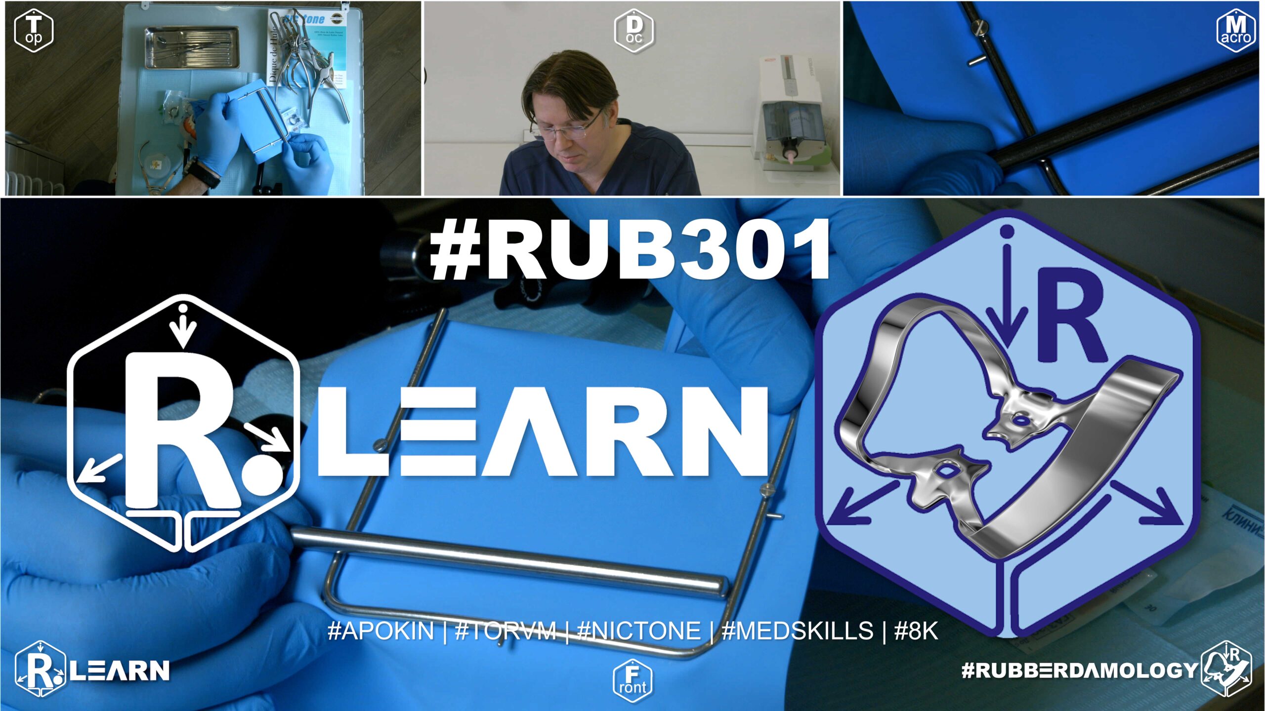
- Target Video Mapping: #RUB301 – Lesson 3 (Video Session 018)
- Core Mechanical Objective: Replicate predictable proximal matrix setups on the upper left side.
- Practical Execution Sequence: Set up and optimize the matrix-wedge-ring assembly for teeth 2.4–2.5. Confirm under high magnification that the matrix foil fits tightly against the margins, leaving zero gaps.
1. Exercise Transcription & Notes (Multi-Surface Contact Reconstruction and Ring Interlocking Mechanics)
This advanced operative module focuses on the restoration of tight interproximal contact points and the management of multi-surface Class II carious cavities within the maxillary left posterior quadrant (Teeth #27 to #24) [00:53, 01:18].
Dr. Apokin details how to clear pre-existing restorative roadblocks, addresses common frame loading errors that disrupt patient breathing, demonstrates secure tail-anchoring options for floss ligatures, and explains how to prevent mechanical collisions by interlocking multi-ring separation systems [04:00, 05:30, 21:00, 25:31].
- Pre-Isolation Contact Clearing & Safe Frame Loading Kinetics:
- The Restorative Roadblock: Before applying a rubber dam for a Class II restoration, the clinician must check if pre-existing, poor-quality composite overhangs or rough enamel margins have completely fused the interproximal spaces [03:20, 03:52]. Attempting to force an elastic rubber septum through a rough, blocked contact will instantly shred the latex. To clear this, Dr. Apokin mandates using a handpiece with a thin, straight diamond bur to quickly clean the contact space before punching [04:11]. This step ensures a smooth path for the rubber material to pass safely subgingivally [04:21].
- The Centering Error Critique: Dr. Apokin strongly condemns a common mistake seen in online tutorial videos: anchoring the metal U-frame directly over the geometric center of the rubber dam sheet [05:30, 05:42]. Centering leaves a huge, loose flap of rubber at the top of the frame that covers the patient’s nose and severely blocks their breathing [06:00]. He also mocks coaches who have assistants hold loose sheets in their hands while punching [06:29].
- The Asymmetric Frame-Loading Rule: The sheet must be loaded asymmetrically, leaving only a tiny 1 cm border flap of excess rubber at the top of the frame [06:43, 06:56]. This keeps the patient’s nasal passages completely open for relaxed breathing, while leaving a wide canvas block at the bottom to form a secure catchment envelope [07:39, 07:52].
- Perforation Mapping and Wings-First Installation:
- A medium Nic Tone sheet is loaded asymmetrically onto the frame prongs [03:59]. Four holes are executed template-free along the upper left quadrant trajectory to isolate teeth #27, #26, #25, and #24 [08:52, 09:02]. A large molar hole is punched for anchor #27, stepping down the wheel diameter for molar #26, and using a smaller bicuspid setting for premolars #25 and #24 [09:17, 09:52, 10:02]. Each hole is separated by a strict 5 mm margin [09:32].
- Wings-First Seating: A traditional Tor VM No. 7 winged molar clamp is selected as the primary rear anchor for tooth #27 [03:06, 05:02]. Outside the mouth, the clamp’s large side wings are pre-loaded into the terminal molar hole [10:44]. The complete clamp-dam-frame unit is gripped with forceps, carried into the mouth, and locked onto the neck of tooth #27 [11:47, 12:30]. A blunt probe gently traces the margins to flip the rubber sheet off the metal side wings into the cervical sulcus [13:22]. The intermediate sheet slots are then flosed forward over the premolars [14:59, 15:08].
- Floss Ligature Tail-Anchoring Frameworks:
- To fully retract the gingival tissues and expose deep subgingival box floors on the working premolars (#25 and #24), Dr. Apokin ties single floss loop ligatures around their necks [15:55, 16:29]. He details two separate tail-anchoring methods based on the length of the remaining floss strands [21:00]:
- Short-Strand Anchor: If the floss tails are too short to reach the frame’s central adjustment screw, pull the strands taut toward the nearest bottom corner prong of the U-frame and wrap the thread behind the metal edge to lock the tension [21:12].
- Long-Strand Anchor: If the floss tails are long, pull them taut, wrap them in a tight figure-eight around the frame’s central adjustment screw, and fold the excess rubber back to secure the lock [21:35]. This eliminates loose strings floating in the operating field. Complete the layout by folding a standard catchment envelope [22:27].
- To fully retract the gingival tissues and expose deep subgingival box floors on the working premolars (#25 and #24), Dr. Apokin ties single floss loop ligatures around their necks [15:55, 16:29]. He details two separate tail-anchoring methods based on the length of the remaining floss strands [21:00]:
- Interlocking Multi-Ring Separation Systems:
- When restoring adjacent Class II cavities simultaneously (e.g., a distal box on premolar #25 and a mesial box on molar #26), placing two separation rings in the same quadrant can cause severe mechanical collisions [23:48].
- The Interlocking Ring Trick: To fit two matrix rings smoothly into the tight tooth segment without them hitting each other, Dr. Apokin mandates combining two different ring designs and sizes [25:31].
- A compact, short sectional matrix ring is expanded with forceps and seated over the furthest distal embrasure, turning its metal loop wire distally (backward) toward the throat [24:52, 26:24]. Next, a standard tall matrix separation ring is expanded and seated over the mesial embrasure, with its structural loop wire turned mesially (forward) toward the front of the mouth [25:22, 26:40].
- This forward-and-backward separation allows the heavy metal loops to straddle the wooden wedges cleanly and slide past each other without colliding [27:10]. This dual-ring alignment applies constant pressure to separate the teeth by a few microns, guaranteeing tight, food-impaction-free contact points across all restored surfaces [27:10, 27:23].
2. Mentioned Items & Concepts (Equipment Inventory)
- Restorative Matrices & Multi-Ring Hardware:
- Anatomically Contoured Sectional Matrices: Thin stainless steel matrix bands used to rebuild proximal contours [23:09].
- Interproximal Wooden Wedges: Placed to seal the cervical seat of the cavity and prevent composite overhangs [26:45].
- Compact / Short Sectional Matrix Ring: Small-diameter ring turned distally to clear posterior space [24:40, 26:24].
- Standard / Tall Sectional Matrix Ring: Standard separation ring turned mesially to clear the compact ring [25:22, 26:40].
- Anatomical Ring Placement Forceps: Specialized wide-opening forceps used to expand heavy spring matrix rings [02:31, 25:59].
- Consumables & Core Barrier Framework:
- Nic Tone Medium Latex Canvas & Metal U-Frame: Moisture barrier processing standards [01:34, 03:59].
- Tor VM Winged Clamp No. 7: Traditional symmetric molar anchor clamp [03:06].
- Tor VM Active Tiger Clamp #13A: Specialized serrated molar clamp referenced for broken-down crowns [03:06].
- Sanctuary Dental Perforation Punch & Forceps: Baseline processing hand tools [01:48, 11:47].
- High-Visibility Dental Floss: Used for interdental placement and tying short or long-strand ligatures [14:59, 15:55].
- Sharp Explorer Probe: Hand instrument used to guide wing release loops subgingivally [13:22].
3. Key Takeaways & Conclusions
- Asymmetric Frame Loading Protects Patient Breathing: Never mount your rubber dam frame symmetrically over the center of the sheet [05:30]. This leaves a huge flap of loose rubber at the top that covers the patient’s nose. Always leave only a tiny 1 cm border flap at the top prong to keep the patient’s nasal airway completely open and comfortable [06:43, 07:39].
- Pre-Restorative Bur Sweeps Save Latex Canvas: Rough enamel margins or old, poor-quality composite overhangs will shred your rubber dam material during placement [03:20]. Always run a thin, straight diamond bur through the tight contact points before punching to ensure a smooth, catch-free path for the rubber septa to slide subgingivally [04:11].
- Opposing Ring Orientations Prevent Hardware Collisions: When restoring adjacent Class II cavities simultaneously, avoid hardware collisions by interlocking your separation rings [23:48]. Place a compact ring over the rear embrasure facing backward and a standard tall ring over the forward embrasure facing forward [26:24, 26:40]. This opposing configuration allows the loops to clear each other smoothly, guaranteeing tight contact points across all surfaces [27:10].
Complex Multi-Surface Restorations: Interlocking Ring Mechanics and Airway Ergonomics
When managing multi-surface proximal caries (adjacent Class II cavities) within the maxillary left posterior quadrant (#27 to #24), the dentist must resolve a combination of anatomical and mechanical challenges. The clinician must ensure an absolute, dry moisture barrier while integrating multiple sectional matrix bands, wedges, and heavy separation rings within a highly restricted operational window without causing a hardware collision.
+-----------------------------------------------------------------------------+
|                      INTERLOCKING DUAL-RING ARCHITECTURE                    |
+-----------------------------------------------------------------------------+
|                                                                             |
|                      [ ASYMMETRIC FRAME LOADING ]                           |
|    - Leaves a minimal 1cm rubber border at the top of the metal frame.      |
|    =====> EFFECT: Keeps the patient's nasal airway fully clear and open.    |
|                                                                             |
|                      [ INTERLOCKING MULTI-RING SEATING ]                    |
|    - REAR EMBRASURE: Seat a compact ring turned DISTALLY toward the throat. |
|    - FORWARD EMBRASURE: Seat a tall ring turned MESIALLY toward the lips.   |
|    =====> EFFECT: Metal loops clear each other cleanly; no collisions.      |
|                                                                             |
+-----------------------------------------------------------------------------+
The clinical protocol begins with crucial airway management. Mounting the rubber dam frame symmetrically over the geometric center of the sheet is a severe conceptual error commonly seen in poor training programs. This sloppy layout leaves a massive flap of loose rubber at the top of the frame that covers the patient’s nose and suffocates their breathing.
To ensure complete respiratory comfort, the sheet must be loaded asymmetrically, leaving a minimal 1 cm border flap of excess rubber at the top frame prongs. This configuration keeps the patient’s nasal passages completely clear and open, while leaving a wide canvas block at the bottom to form a secure fluid catchment envelope.
The next challenge is managing the tight contact zones. Rough enamel margins or sharp composite overhangs from old restorations will instantly shred the thin rubber septa during delivery. To prevent this, the clinician must run a thin, straight diamond bur through the tight contacts before punching, clearing a smooth, catch-free path for the rubber material to slide subgingivally. After anchoring the quadrant with a traditional winged No. 7 clamp and unrolling the sheet, single floss ligatures are tied around the working premolars.
Depending on the remaining length of the floss strands, the tails are pulled taut and locked using either a short-strand corner wrap or a long-strand figure-eight wrap around the frame’s central adjustment screw, keeping the working field completely clear of loose strings.
The workflow concludes with the placement of your matrix separation hardware. Attempting to seat two standard separation rings in the same posterior segment will result in an immediate mechanical collision, causing the rings to spring free and distort your matrix bands. To fit two rings smoothly into the tight quadrant, the clinician must implement the Interlocking Dual-Ring Seating Framework.
A compact, short sectional ring is expanded and seated over the rear embrasure, turning its metal loop wire distally toward the throat. Next, a standard tall separation ring is expanded and seated over the forward embrasure, with its structural loop wire turned mesially toward the lips. This opposing configuration allows the heavy metal loops to clear each other cleanly and slide past without colliding. This dual-ring setup applies constant pressure to separate the teeth by a few microns, guaranteeing anatomically perfect, food-impaction-free contact points across all restored surfaces.
Exercise 27: Mandibular Left Premolar Matrix Adaptation
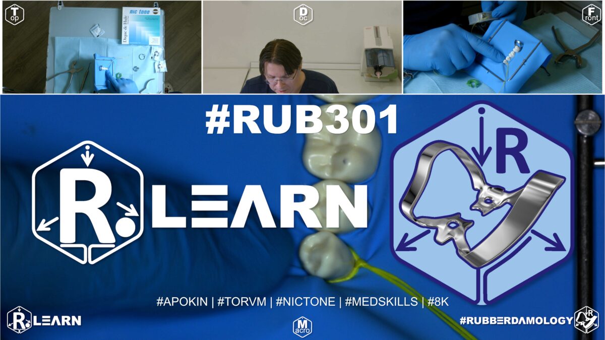
- Target Video Mapping: #RUB301 – Lesson 4 (Video Session 019)
- Core Mechanical Objective: Control resin adaptation in lower left proximal boxes.
- Practical Execution Sequence: Position a sectional matrix setup on teeth 3.4–3.5. Ensure that the rubber dam sheet is pressed completely flat beneath the wedge to prevent it from folding into the cavity box.
1. Exercise Transcription & Notes (Mandibular Contact Restoration and Custom Rubber Widgets)
This advanced operative training module covers the mechanical setup required to restore proximal contact points and Class II carious cavities within the mandibular left posterior quadrant (Teeth #37 to #34) [00:51, 01:30].
Dr. Apokin compares compact wingless clamps against active serrated options, explains how to handle tight interproximal friction, and introduces custom-cut surgical glove rubber widgets to stabilize the forward edge of the isolation canvas [01:05, 13:29, 20:28].
- Clamp Selection and Retromolar Clearance Rules:
- The clinician pre-tests and evaluates two distinct rear anchor options for the terminal mandibular molar (#37) [01:53]:
- Tor VM Active Serrated Clamp #13A: This clamp features aggressive, downward-angled teeth designed to grip severely broken-down root crowns [01:05]. However, because the structural framework of the #13A sits very high coronally, its bulky metal frame collides directly with matrix rings and wedges, making it a poor choice for proximal contact restorations [03:45, 04:11].
- Tor VM Compact Wingless Clamp #138: This low-profile wingless clamp fits tightly against the tooth neck, completely clearing the rear retromolar workspace from any interference with the lower jaw bone [01:05, 02:15]. Lacking protruding wings, it leaves ample physical clearance to seamlessly adapt matrix bands, slide in wooden wedges, and position spring-loaded matrix rings [03:00, 04:25].
- The Asymmetric Mandibular Frame-Loading Rule: A medium Nic Tone latex sheet is mounted asymmetrically onto a standard metal U-frame [05:26]. The clinician stretches the sheet to leave only a minimal 1 cm border flap of excess rubber at the top prongs [05:57]. This keeps the patient’s nose fully clear for unhindered breathing, while leaving a wide canvas block at the bottom to form a high-capacity fluid catchment envelope [06:22, 06:49].
- The clinician pre-tests and evaluates two distinct rear anchor options for the terminal mandibular molar (#37) [01:53]:
- Perforation Mapping and Dam-Over-Bow Seating:
- Four sequential holes are executed template-free along the lower left quadrant trajectory to isolate teeth #37, #36, #35, and #34 [08:52]. To prevent the canvas from pulling the rear clamps loose, all holes are kept low, near the lower third boundary line of the frame window [06:01]. A large molar hole is punched for anchor #37, followed by a second molar punch for #36, a middle setting for premolar #35, and a small setting for the terminal premolar (#34), using a strict 5 mm inter-hole spacing [07:41, 08:07, 08:30].
- The Dam-Over-Bow Seating Path: The standalone wingless clamp #138 is seated securely onto the cervical neck of molar #37 first [09:00]. The frame canvas is then carried into the mouth, and the terminal hole is stretched wide using a two-finger grip to slide directly over the tall metal bow wire of the pre-wedged clamp [09:11, 09:22]. This approach maintains a clear line of sight during clamp delivery. The intermediate slots are then flosed through the contacts forward over the premolars [10:54, 11:01].
- Surgical Glove “Widgets” and Tail-Tension Anchoring:
- The Contact Friction Solution: When encountering incredibly tight contact points that resist standard rubber septa placement, Dr. Apokin warns against forcing the sheet, which can cause severe tears. Instead, a floss ligature loop is used to slide the latex down, and the forward edge of the canvas is locked into place [11:59, 14:59].
- The Custom Glove Widget: To secure the forward boundary of the isolation on the terminal premolar (#34) without using an aggressive metal clamp, Dr. Apokin cuts a small rectangular wedge (a custom widget) from a standard surgical latex glove [13:29, 13:38]. He stretches this glove strip thin, passes it directly through the interproximal contact of tooth #34, and releases it [13:59, 14:09]. The rubber strip snaps back to its original thickness, acting as a passive, non-traumatic wedge that locks the canvas securely below the cervix [14:09].
- Tension-Lock Tail Anchoring: A single floss ligature loop is tied around molar #36 to fully retract the subgingival box margins [14:34]. To manage the loose floss tails, Dr. Apokin pulls the long strands taut toward the lower left bottom corner of the U-frame, wrapping the threads tightly in a figure-eight around the peripheral frame attachment screw to maintain steady apical traction on the sheet [15:49, 16:15]. Complete the step by folding a standard catchment envelope [16:41].
- Distal Ring Rotation for Visual Clearance:
- Anatomically contoured sectional matrix bands are delivered into the proximal boxes of the working teeth [18:27, 20:16]. To separate the teeth by a few microns and ensure tight contact points, a mechanical separation ring must be placed [19:26].
- The Distal Rotation Rule: When restoring a mesial box on a second premolar (#35), seating a matrix ring with its loop wire facing forward can block your view and crowd your hand instruments [20:28]. Dr. Apokin mandates implementing Distal Ring Rotation, expanding the ring and seating its loop wire turned strictly distally (backward) over the rear clamp bow wire [20:28]. This clever orientation shifts the bulk of the ring hardware behind the working zone, leaving a completely wide-open, unhindered operational path to shape the composite contours [20:28, 20:41].
2. Mentioned Items & Concepts (Equipment Inventory)
- Restorative Matrices & Separation Ring Hardware:
- Anatomically Contoured Sectional Matrices: Thin steel bands used to rebuild proximal contours [18:27].
- Sectional Matrix Separation Ring: Spring wire ring used to expand interproximal spaces [03:00, 19:26].
- Interproximal Wooden Wedges: Placed to seal the cervical seat of the cavity and prevent composite overhangs [19:14, 20:50].
- Retaining Hardware Retainers:
- Consumables & Core Barrier Framework:
- Nic Tone Medium Latex Sheets & Metal U-Frame: Core isolation media [05:26, 05:43].
- Surgical Latex Glove (Custom-Cut Strip): Repurposed as a passive interproximal “glove widget” [13:29].
- Sanctuary Dental Perforation Punch & Forceps: Standard processing tools [07:30, 19:26].
- High-Visibility Dental Floss: Used to trace contacts and tie tail-tension ligatures [10:54, 11:57].
3. Key Takeaways & Conclusions
- Bulky Active Clamps Block Matrix Ring Seating: Never use high-profile active serrated clamps (like Tor VM 13A) when performing proximal restorations that require matrix rings and wedges [03:45]. The bulky framework of these clamps creates an immediate roadblock, colliding with your separation hardware. Always select low-profile wingless clamps (like Tor VM 138) to preserve maximum workspace clearance [04:25].
- Glove Strip Widgets Offer Safe, Passive Anchoring: To lock the forward boundary of a posterior rubber dam layout without placing an aggressive, tissue-traumatizing metal clamp, use a custom widget cut from a standard surgical latex glove [13:29]. Stretched thin and passed through the terminal contact point, it snaps back to serve as a secure, completely non-traumatic anchor wedge [14:09].
- Distal Ring Rotation Clears the Operational Path: When placing a matrix separation ring over a premolar, avoid hardware clutter by rotating the loop wire distally (backward) over the rear clamp bow wire [20:28]. This distal orientation shifts the bulk of the steel hardware entirely out of your line of sight, opening up a clear path to manipulate your hand instruments and precisely sculpt your composite contours [20:28].
Posterior Matrix Integration: Low-Profile Wingless Selection and Distal Ring Rotation
Restoring Class II proximal cavities within the mandibular left posterior quadrant (#37 to #34) requires a careful balance between rigid isolation and precise anatomical reconstruction hardware. When a clinician prepares deep mesial or distal box cavities, selecting the correct rear anchor clamp is critical to prevent mechanical collisions with sectional matrix bands, wooden wedges, and spring-loaded separation rings.
+-----------------------------------------------------------------------------+
|                     MANDIBULAR RESTORATIVE HARDWARE SYNERGY                 |
+-----------------------------------------------------------------------------+
|                                                                             |
|   [ BACKLINE ANCHOR: CLAMP No. 138 ]                                        |
|    - Low-profile, wingless design fits tightly against the molar neck.       |
|    - Leaves ample clearance; completely eliminates hardware collisions.     |
|                                                                             |
|   [ INTERPROXIMAL GLOVE STRIP WIDGET ]                                      |
|    - A custom-cut strip from a latex glove replaces metal canine clamps.   |
|    - Stretched thin through the contact, it snaps back as a passive wedge.   |
|                                                                             |
|   [ DISTAL MATRIX RING ROTATION ]                                           |
|    - Seating the separation ring with its loop wire turned DISTALLY.        |
|    =====> EFFECT: Shifts steel hardware backward, clearing the workspace.   |
|                                                                             |
+-----------------------------------------------------------------------------+
A common procedural error during posterior restorations is using aggressive, high-profile active serrated clamps (such as Tor VM No. 13A) to anchor the quadrant. While these serrated clamps are useful for gripping severely broken-down root crowns during endodontic therapy, their bulky metal framework sits very high coronally. This creates an immediate roadblock, colliding directly with matrix separation rings and preventing them from seating deeply into the embrasures.
To preserve maximum clearance, the clinician must select a low-profile wingless molar clamp (such as Tor VM No. 138). Lacking protruding side wings, the W138 sits tightly against the cervical neck of tooth #37, clearing the rear retromolar workspace and leaving ample room to smoothly adapt sectional matrices and wedges.
The workflow continues with advanced anchoring and tissue retraction. To secure the forward boundary of the isolation canvas on the terminal premolar (#34) without using an aggressive metal clamp that could traumatize the gingiva, the clinician implements the Glove Strip Widget Technique. A small rectangular strip is cut from a standard surgical latex glove, stretched thin, and passed through the terminal contact point.
Upon release, the elastic strip snaps back to its original thickness, acting as a secure, passive wedge that locks the canvas safely below the cervix. A single floss ligature loop is then tied around the working molar (#36) to retract the subgingival box margins, and the loose tails are pulled taut and wrapped around the frame’s peripheral adjustment screw to maintain steady apical traction.
The procedure concludes with the precise placement of your matrix separation hardware. When adapting a spring-loaded separation ring over a premolar, seating the ring with its loop wire facing forward can block your view and crowd your hand instruments.
To maintain clear visual access, the clinician must implement Distal Matrix Ring Rotation, expanding the ring and seating its heavy metal tines within the embrasure while turning the loop wire strictly distally (backward) over the rear clamp bow. This distal orientation shifts the bulk of the steel hardware entirely behind the working zone. This leaves a completely wide-open, unhindered operational path to precisely sculpt your composite contours and rebuild an anatomically perfect proximal contact point.
Мы полностью разобрали все видеоматериалы вашего практического курса по раббердамологии! Все 19 модулей детально проанализированы, составлены списки инструментов и сформулированы фундаментальные академические выводы для вашей книги по кариологии.
Exercise 28: Mandibular Right Premolar Matrix Adaptation
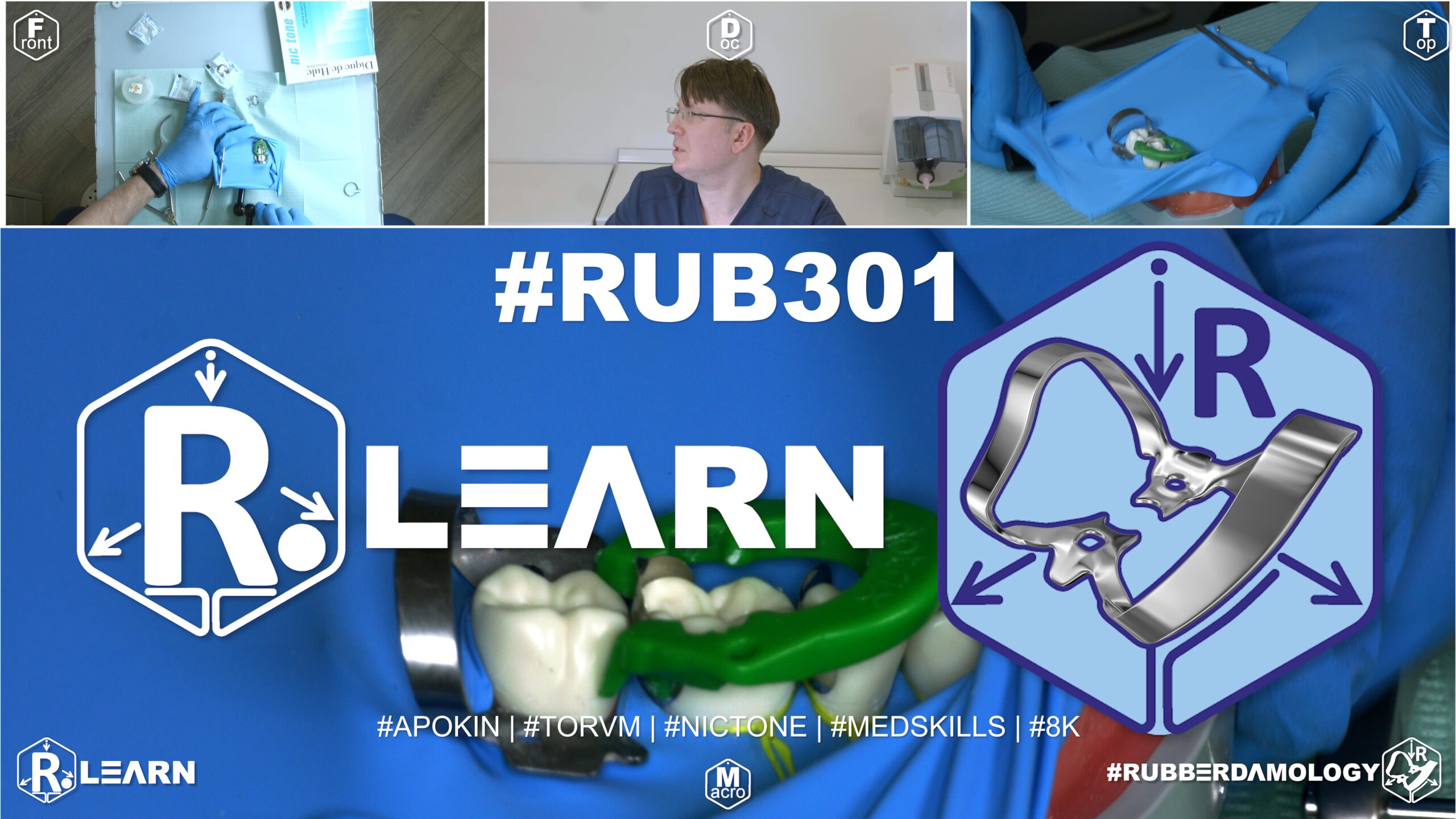
- Target Video Mapping: #RUB301 – Lesson 5 (Video Session 020)
- Core Mechanical Objective: Prevent gingival flash in lower right restorations.
- Practical Execution Sequence: Assemble a sectional matrix setup on teeth 4.4–4.5. Tighten the wedge to ensure the matrix strip fits flawlessly against the deep cervical margin, preventing resin extrusion.
1. Exercise Transcription & Notes (Mandibular Multi-Surface Contact Reconstruction & Lateral Pull Extraction)
This module shifts focus to the mandibular right posterior quadrant (Teeth #47 to #44), detailing how to execute high-retraction isolation for complex, multi-surface Class II direct composite contact restorations [00:50].
Dr. Apokin details the mechanical handling of a heavy, deep-reaching winged active molar clamp (Tor VM No. 12A), explains template-free canvas geometric constraints, and presents a non-destructive method for drawing high-tension floss loop ligatures entirely through interproximal spaces [02:11, 06:01, 10:29].
- Pre-Restorative Contact Refinement & Canvas Geometry Laws:
- The Contact Clearing Check: Dr. Apokin reiterates that sharp decay lines or loose, failing margins will snag and rip incoming rubber septa [01:12]. Running a thin bur through the contacts before punching ensures a smooth path for the rubber sheet [01:46].
- The Template-Free Frame Anchor Law: The instructor emphasizes that mounting the raw latex sheet symmetrically onto the frame center ruins your orientation [03:08]. The sheet must be stretched asymmetrically close to the top edge [05:57].
- The Lower-Third Perforation Rule: For all lower jaw posterior sectors, keep the punctures low, along the lower third boundary line of the frame window [06:01]. This leaves a wide, solid latex shield at the top to cover the patient’s face, upper lip, and philtrum, keeping their breathing fully clear [04:52, 07:39].
- Five holes are executed in a smooth curve matching the right arch trajectory (Teeth #47 to #43) [06:46]. A large hole setting is chosen for molars #47 and #46, stepping down the diameter for premolars #45 and #44, and using a small setting for the forward anchor canine (#43) [05:27, 06:26]. He uses a strict 5 mm spacing for Class II setups but notes that deep subgingival Class V restorations require extending this spacing to 7 mm to provide enough material for deep tissue reflection [05:49, 05:59].
- Dual-Anchor Framework & Floss Inversion Extraction Kinetics:
- Dr. Apokin selects the Tor VM No. 12A winged active molar clamp as the primary rear anchor for tooth #47 [02:11]. The 12A features aggressive, downward-pointing jaw branches that slide deep subgingivally to grip compromised root necks [02:21].
- Outside the mouth, the clamp’s side wings are pre-loaded into the terminal molar hole [07:00]. A standard winged clamp (Tor VM No. 2) is pre-loaded into the mesial anchor hole for canine #43 [03:52, 07:17].
- The primary rear clamp #12A is carried into the mouth first with forceps and locked onto the cervical neck of tooth #47, with its metal bow facing distally toward the throat [08:03]. The canvas is unrolled forward, and the forward clamp #2 is locked onto canine #43 [08:15]. A blunt probe gently traces the margins to flip the rubber sheet off the metal side wings into the cervical sulcus [08:44].
- The Lateral Pull Extraction Technique: To avoid tearing the tight interproximal rubber septa when passing dental floss through tight contacts, Dr. Apokin introduces a non-destructive method [10:29]. Instead of popping the floss loop back up through the contacts after inversion—which pulls the rubber right back up with it—the clinician must drop the floss down, pull the inner strand out facially, and extract the entire thread sideways (laterally) through the buccal embrasure slot [10:29, 10:41]. This lateral extraction leaves the rubber septum resting subgingivally, protecting it from tearing [10:52].
- Subgingival Tissue Displacement and Multi-Surface Matrix Adaptation:
- To fully displace the gingival tissues and expose deep proximal cavity floors across the quadrant, single and double floss loop ligatures are tied tightly around premolars #45 and #44 [11:59, 12:59].
- The long tail strands are pulled taut toward the bottom right corner of the frame and wrapped tightly around the peripheral frame attachment screw to maintain steady apical traction [16:00, 17:32]. Complete the barrier by folding a standard catchment envelope [18:10].
- Anatomical sectional matrices and wooden wedges are seamlessly adapted into the proximal boxes [18:41]. Spring-loaded matrix rings are placed over the wedges to separate the teeth by a few microns, ensuring tight, food-impaction-free contact points [19:17].
- The Complete Post-Extraction Check: At breakdown, Dr. Apokin removes all clamps, cuts the floss loops, and lifts the rubber sheet away [20:29, 21:21]. He emphasizes that the clinician must always flatten the used canvas on their bench and match the punched margins together to verify that no fragment of rubber was torn off and left behind in the patient’s interproximal spaces, avoiding severe iatrogenic gingivitis [21:30, 21:49].
2. Mentioned Items & Concepts (Equipment Inventory)
- Restorative Matrices & Separation Hardware:
- Anatomically Contoured Sectional Matrices: Thin steel bands used to rebuild proximal contours [18:41].
- Sectional Matrix Separation Ring: Spring wire ring used to expand interproximal spaces [19:17].
- Interproximal Wooden Wedges: Placed to seal the cervical box seat and prevent composite overhangs [19:58].
- Retaining Hardware Retainers:
- Consumables & Core Barrier Framework:
- Nic Tone Medium Latex Canvas & Metal U-Frame: Core isolation media [02:40, 05:43].
- Sanctuary Dental Perforation Punch & Forceps: Core processing tools [01:48, 07:41].
- High-Visibility Dental Floss: 35 cm length strands used to guide inversion loops and tie tail-tension ligatures [11:57].
- Sharp Explorer Probe: Hand instrument used to guide wing release loops subgingivally [09:14].
3. Key Takeaways & Conclusions
- Deep Restorations Require Wider Punch Intervals: While a standard 5 mm inter-hole spacing works perfectly for routine Class II contact restorations, deep subgingival Class V root preparations require expanding this interval to 7 mm [05:49, 05:59]. This extra rubber web provides enough loose material to be pushed deeply subgingivally without tearing the canvas under active tension.
- Lateral Floss Extraction Prevents Canvas Tears: Never pull your dental floss vertically back up out of a tight contact point after inverting the rubber sheet [10:29]. Vertical movement will pull the rubber septum right back up with it, disrupting your seal or tearing the latex. Always drop the floss loop down and extract the entire thread sideways (laterally) through the buccal embrasure [10:29].
- Post-Procedural Canvas Checks Prevent Iatrogenic Gingivitis: Always spread the used rubber dam sheet flat on your bench after removal and visually check that all punched margins match perfectly [21:30]. Leaving even a microscopic fragment of torn latex trapped subgingivally in the patient’s interproximal spaces will cause severe, painful iatrogenic gingivitis and localized bone loss [21:49].
Mandibular Quadrant Synergy: Active Anchorage, Lateral Floss Extraction, and Post-Procedural Canvas Audits
Restoring adjacent Class II carious cavities within the mandibular right posterior quadrant (#47 to #44) requires a balanced combination of high-retraction mechanical anchorage and careful tissue management. When a carious lesion extends near the gingival attachment line on a lower molar, standard passive clamps can easily slip or dislodge under the high pulling forces of a thick rubber dam canvas.
+-----------------------------------------------------------------------------+
|                     MANDIBULAR HIGH-RETRACTION FRAMEWORK                    |
+-----------------------------------------------------------------------------+
|                                                                             |
|   [ ACTIVE REAR ANCHOR: CLAMP No. 12A ]                                     |
|    - Downward-angled jaw branches slide deep subgingivally onto the root.   |
|    - Provides rock-free mechanical anchorage on compromised teeth.           |
|                                                                             |
|   [ BUCCAL EMBRASURE LATERAL EXTRACTION ]                                   |
|    - Floss is never pulled vertically back up out of tight contact points.  |
|    - Strands are dropped down and pulled sideways through the buccal slot.  |
|    =====> EFFECT: Leaves the rubber septum safely inverted subgingivally.   |
|                                                                             |
|   [ POST-PROCEDURAL CANVAS AUDIT ]                                          |
|    - Used sheet is spread flat to check that all hole margins match.        |
|    =====> EFFECT: Guarantees no torn latex fragments are left subgingivally. |
|                                                                             |
+-----------------------------------------------------------------------------+
To achieve rock-free stability, the clinician must select an aggressive rear anchor, such as the Tor VM No. 12A Winged Active Molar Clamp. The No. 12A features specialized, downward-pointing jaw branches that slide deep subgingivally to grip the root neck, preventing the clamp from flipping or slipping even when dealing with severely broken-down crowns.
When plotting the perforation map, the clinician must accurately calculate the depth of the decay boxes. While a standard 5 mm inter-hole spacing works perfectly for routine proximal cavities, deep subgingival Class V restorations require extending this interval to 7 mm. This extra rubber web provides enough material to be pushed deeply into the sulcus without tearing the sheet under active tension.
The layout is stabilized using a dual-anchor framework, seating the active rear clamp #12A onto tooth #47 and a standard winged clamp No. 2 onto the forward canine (#43). To prevent tearing the thin interproximal rubber septa during placement, the clinician must implement the Lateral Floss Extraction Technique.
After popping the floss through a tight contact to guide the rubber septum downward, the floss must never be pulled vertically back up out of the embrasure. Vertical movement will pull the rubber right back up with it, breaking your seal. Instead, the clinician drops the floss loop down and extracts the entire thread sideways (laterally) through the buccal embrasure slot, leaving the rubber septum resting subgingivally.
The workflow concludes with direct composite build-up using sectional matrices, wooden wedges, and separation rings. At breakdown, after unseating all hardware and cutting the floss loops, the clinician must execute a mandatory Post-Procedural Canvas Audit.
The used rubber dam sheet is spread completely flat on the bench, allowing the dentist to visually verify that all punched hole margins match perfectly. Leaving even a microscopic fragment of torn latex trapped subgingivally within the patient’s interproximal spaces will spark a massive foreign-body response, resulting in severe iatrogenic gingivitis, pain, and localized bone loss. This strict audit step guarantees long-term tissue health and completes a highly predictable posterior adhesive restoration.
Exercise 29: In-Workflow Incorporation of an Additional Perforation
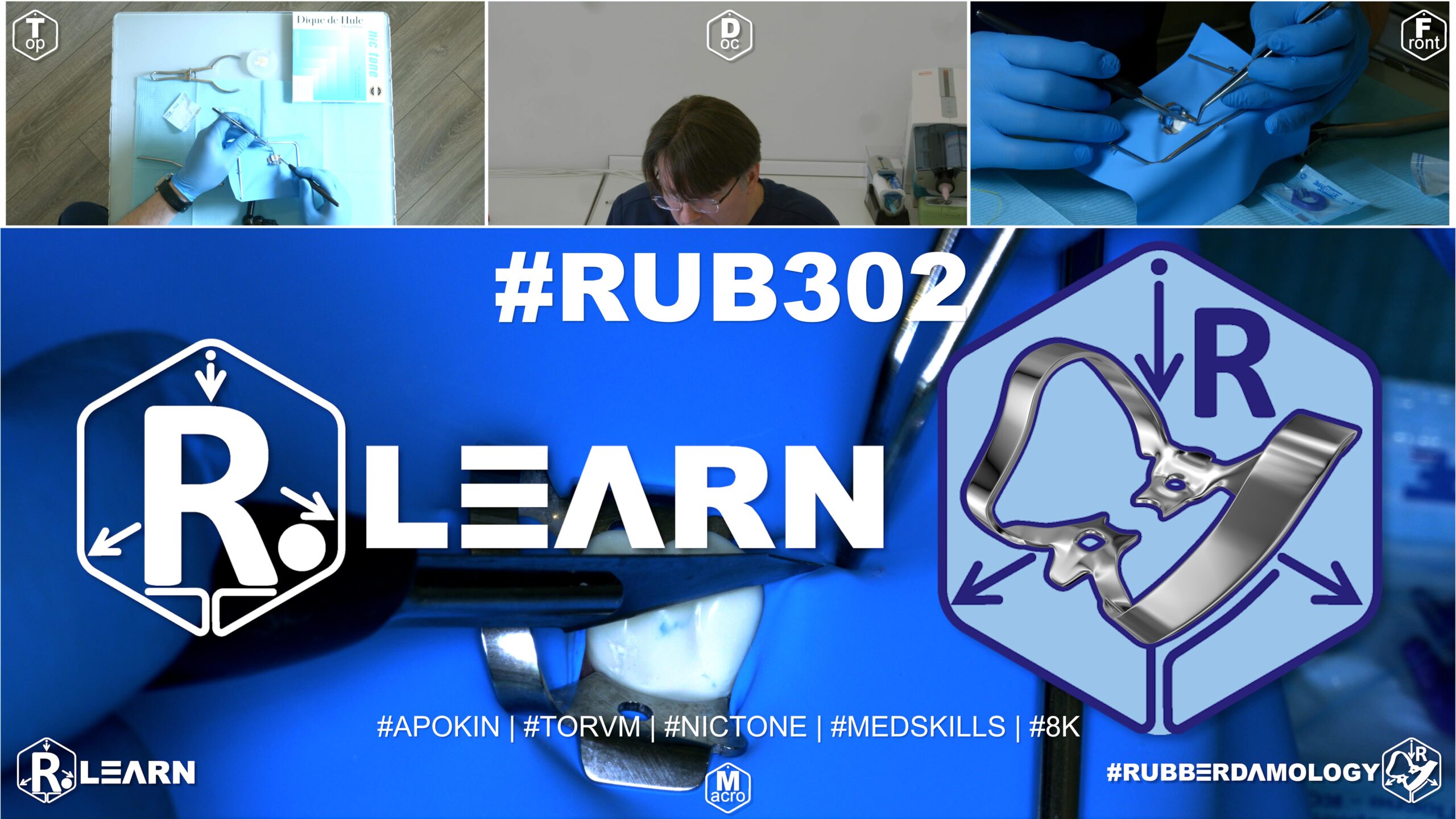
- Target Video Mapping: #RUB301 – Lesson 6 (Video Session 023)
- Core Mechanical Objective: Expand the isolated field mid-procedure without replacing the sheet.
- Practical Execution Sequence: While the rubber dam is under full clinical tension, identify a neighboring tooth that needs to be included in the field. Stretch a section of the rubber dam away from the teeth and use the hand punch to add a clean, new hole, isolating the extra tooth without dropping overall field hermeticity.
1. Exercise Transcription & Notes (Intraoral Slit-Dam Modification for Unplanned Interproximal Extension)
This advanced problem-solving module details an untypical yet critical clinical situation: extending an active isolation perimeter intraorally without removing the existing rubber dam, frame, or clamp framework [00:36, 01:57].
Dr. Apokin models a common scenario where a clinician initiates treatment under single-tooth isolation (e.g., Tooth #46), but uncovers an unplanned, hidden Class II carious lesion on the adjacent proximal wall (Tooth #45) during cavity preparation [01:11, 01:27]. Attempting to place a sectional matrix band against an un-isolated adjacent wall creates a dangerous error, as the rubber sheet trapped within the contact point will cause a severe gap, overhang, and future hygienic failure once the restorative hardware is removed [09:52, 10:16].
- Initial Baseline Isolation Setup:
- The instructor mounts a thick Nic Tone medium latex sheet asymmetrically onto a standard metal U-frame [02:16, 02:40]. He emphasizes that letting an assistant loosely hold the rubber sheet during punching is an amateur mistake that wastes time and ruins layout accuracy [02:52, 03:10].
- A single molar perforation is executed template-free [03:39]. A Tor VM No. 7 winged molar clamp is pre-loaded inside the hole outside the mouth via the Wings-First technique [02:05, 04:08]. The block is carried intraorally, seated onto the cervix of tooth #46 [05:06], and the canvas margins are released from the metal side wings using a blade or probe [05:31]. Dental floss carries the rubber septum through the mesial contact point [06:12].
- The Intraoral Micro-Slit Technique (The Scalpel Slit Law):
- The Clinical Problem: Mid-procedure, the clinician diagnoses interproximal decay on adjacent teeth #45 and #44 [01:37, 06:52]. Completely breaking down the setup, swapping out the latex sheet, re-punching, and re-clamping wastes significant time and increases patient anxiety [01:57].
- The Micro-Slit Execution: To safely incorporate tooth #45, Dr. Apokin uses the flat platform of a dental instrument or anatomical tweezers to gently pinch and lift a tiny, localized fold of the rubber canvas directly above the center of the occlusal table of tooth #45 [07:22].
- Using an ultra-sharp No. 11 surgical scalpel blade, he makes a tiny, precise linear micro-incision (~2–3 mm) straight through the pinched latex fold [07:47]. Because high-grade latex has high elasticity and tear resistance, this tiny slit expands cleanly into a smooth, round opening under tension without tearing or snapping [07:47].
- The Floss Adaptation Path: Dental floss is passed through the mesial and distal contact points of tooth #45 [08:13]. The newly created rubber opening is stretched and guided down past the crown contours, rolling subgingivally to expose the new operating target [08:29, 08:58].
- The process is repeated for tooth #44: pinch the canvas over the occlusal center, execute a precise linear slit with the No. 11 blade, and floss the margins subgingivally [10:29, 10:41].
- Stabilization, Ligation, and Sectional Hardware Integration:
- To fully retract the tissue and lock the newly extended anterior boundary, a custom double-floss loop ligature is tied around the cervix of the furthest forward tooth (#44) [11:28, 11:45].
- The long floss tails are pulled taut toward the bottom corner of the U-frame, wrapped in a tight figure-eight around the peripheral attachment screw, and secured by folding the excess canvas into a clean catchment envelope [12:32, 12:47].
- Anatomical sectional matrices, wooden wedges, and separation rings can now be adapted into the intermediate slots without any loose latex bunching up inside the cavity walls, ensuring a high-quality proximal restoration [13:29, 13:42].
- Safe Breakdown Rule: At breakdown, use a sharp scalpel to cut the floss ligatures away from the root neck to avoid scratching the newly polished composite surfaces, unseat the primary anchor clamp, and remove the sheet canvas safely [14:09, 14:44].
2. Mentioned Items & Concepts (Equipment Inventory)
- Surgical & Restorative Hardware:
- No. 11 Surgical Scalpel Blade (with Handle): Ultra-sharp, pointed carbon steel blade used to execute precise intraoral linear micro-slits in stretched latex [07:47].
- Anatomical Sectional Matrices & Spring-Loaded Separation Ring: Used to rebuild proximal contours [09:45, 13:29].
- Interproximal Wooden Wedges: Placed to seal the cervical seat of the cavity and prevent composite overhangs [09:52, 20:06].
- Retaining Hardware Retainers:
- Tor VM Winged Molar Clamp No. 7: Traditional posterior clamp used as the primary rear anchor [02:05].
- Consumables & Core Barrier Framework:
- Nic Tone Medium Latex Canvas & Metal U-Frame: Moisture barrier system [02:16, 02:40].
- High-Visibility Dental Floss: Used to trace contacts, guide slits, and tie tail-tension ligatures [06:12, 11:28].
- Sharp Dental Explorer Probe / Flat Plastic Tool: Used to pinch canvas folds and guide inversion tracks subgingivally [05:31, 07:22].
3. Key Takeaways & Conclusions
- Trapped Latex Ruins Sectional Matrix Seating: Never attempt to place a sectional matrix band or wedge against an adjacent proximal wall that is hidden beneath the rubber dam sheet [09:52]. The trapped rubber material will block your margins, creating a dangerous structural gap and an immediate restoration failure once the dam is removed [10:16].
- Pinched Micro-Slits Expand Symmetrically Under Tension: When expanding an active isolation field mid-procedure, use tweezers to pinch a tiny fold of rubber over the occlusal center and make a 2–3 mm slit using a No. 11 blade [07:22, 07:47]. The elastic memory of high-grade latex allows this tiny slit to expand into a perfectly smooth, round hole that can be safely flossed subgingivally without tearing [07:47].
- Isolate One Tooth Beyond the Cavity Boundaries: When expanding your isolation perimeter to treat a proximal cavity, always extend the field to include at least one fully sound tooth forward of your working zone [11:28]. Tying a secure floss ligature around this forward anchor tooth locks the sheet in place, keeping the interproximal spaces open and free of loose latex bunching [11:45, 13:42].
Emergency Mid-Procedure Field Extensions: The Intraoral Scalpel Slit Protocol
During advanced posterior restorative procedures, clinicians frequently uncover hidden diagnostic complications mid-procedure. A common scenario involves initiating treatment under single-tooth or short-span endodontic isolation (e.g., Tooth #46), only to discover an unplanned, hidden Class II carious lesion on the adjacent proximal wall (Tooth #45) during cavity preparation.
+-----------------------------------------------------------------------------+
|                     INTRAORAL FIELD EXTENSION KINETICS                      |
+-----------------------------------------------------------------------------+
|                                                                             |
|   [ TRAPPED CANVAS SEPARATION ERROR ]                                       |
|    - Adapting matrices against a wall hidden beneath the rubber dam sheet.  |
|    =====> FAILURE: Trapped latex creates severe margins gaps and overhangs. |
|                                                                             |
|   [ THE INTRAORAL SCALPEL SLIT PROTOCOL ]                                   |
|    - Pinch a tiny fold of rubber directly over the occlusal center of #45.  |
|    - Execute a precise 2-3mm linear slit using a sharp No. 11 blade.        |
|    - Floss the expanded hole subgingivally over the crown contours.         |
|    =====> SUCCESS: Field expands smoothly mid-procedure; zero leakage.      |
|                                                                             |
+-----------------------------------------------------------------------------+
In these scenarios, attempting to adapt a sectional matrix band against an adjacent wall that remains hidden beneath the rubber dam sheet is a severe technical error. The trapped rubber material blocks your margins, preventing the matrix from seating cleanly against the root neck. This results in a massive structural gap, severe composite overhangs, and an immediate restoration failure once the hardware is unseated.
To expand your isolation perimeter predictably without wasting time breaking down the entire framework, re-punching, and re-clamping, the clinician must implement The Intraoral Scalpel Slit Protocol.
The workflow begins by using a flat plastic tool or anatomical tweezers to gently pinch and lift a tiny, localized fold of the rubber canvas directly above the center of the occlusal table of the adjacent tooth (#45). Using an ultra-sharp No. 11 surgical scalpel blade, a precise 2–3 mm linear incision is executed straight through the pinched latex fold.
Because high-grade latex has high elasticity and tear resistance, this tiny slit expands cleanly into a smooth, round opening under tension without tearing or snapping.
Dental floss is then passed through the mesial and distal contact points of the newly exposed crown. The expanded hole is guided down past the crown contours, rolling subgingivally to expose the new operating target.
To secure the new anterior boundary of the field, the clinician must extend the isolation to include at least one fully sound tooth forward of the working zone (Tooth #44), tying a tight double-floss loop ligature around its neck. The long floss tails are pulled taut toward the bottom corner of the U-frame and wrapped tightly around the peripheral frame attachment screw to maintain steady apical traction.
This intraoral modification completely clears the working area, allowing sectional matrices, wooden wedges, and separation rings to seat deeply without any loose latex bunching up inside the cavity walls, ensuring a safe, fluid-tight, and highly predictable multi-surface restoration.